An Adjustable Threading Feed Attachment for a Lathe Without Metric Threading Capability
Metric pitch threads, with the exception of the Royal Microscopical Society (RMS) 36 threads per inch Whitworth thread still common on microscope objectives, have long been standard on microscope components. I have used the metric threading patterns on my 1960s vintage Unimat lathe shown in Figure 1, but the patterns for many of the common, fine pitch ISO metric thread pitches were not available for the Unimat. An engineer acquaintance from England also has a strong interest in home shop machining capability. He gave me a copy of an article from the English Magazine Model Engineers Workshop by Ted McDuffie in the autumn 1990 issue. This article, “A Variable Lead Threading Attachment,” was very interesting for me, but I did not at that time own a bench lathe of conventional design that could use this attachment. Since retiring, I completed restoring a Wade 8A precision bench lathe once owned by the United States Navy. I referred back to the McDuffie article to see how I could make a similar attachment for the Wade lathe so I can cut metric threads using the closest thread pitch in the inch system of the Wade quick change gear box. My plan is to make the missing metric thread patterns for my Unimat, because the setup time will be less for metric threading with the Unimat, and its higher spindle speeds are an advantage for making small diameter screws for optical equipment.
Henry Maudslay was the inventor of the first precision lathes in England at the start of the industrial age. Maudslay’s work is described in Robert S. Woodbury, Studies in the History of Machine Tools, The MIT Press, 1961. Woodbury notes that Maudslay used a clever lever system to adjust the thread pitch when making a new lead screw. Maudslay developed precision lead screws with the desired thread pitch and minimal variation in the thread pitch. The McDuffie attachment uses a lever system perhaps inspired by Maudslay’s earlier method. The Wade lathe has a taper turning attachment that I thought could be used to actuate the lead adjusting linkage instead of what McDuffie calls a “variable vane” clamped to a front box way of his Myford Super 7 lathe.
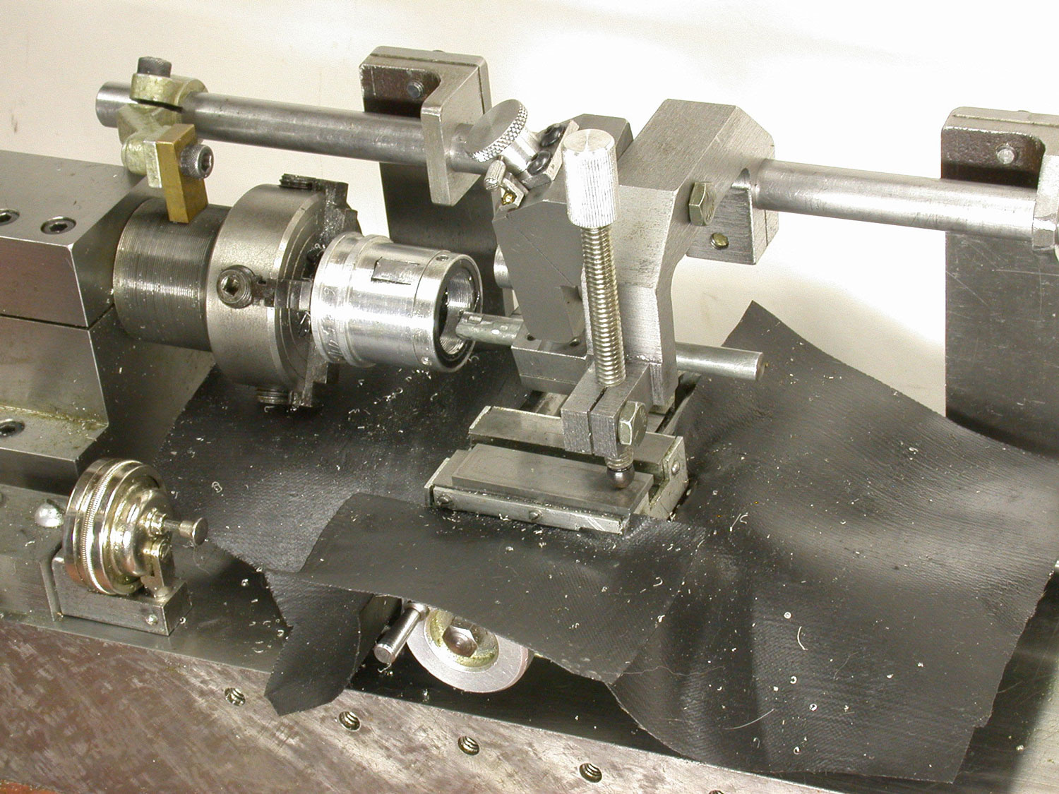
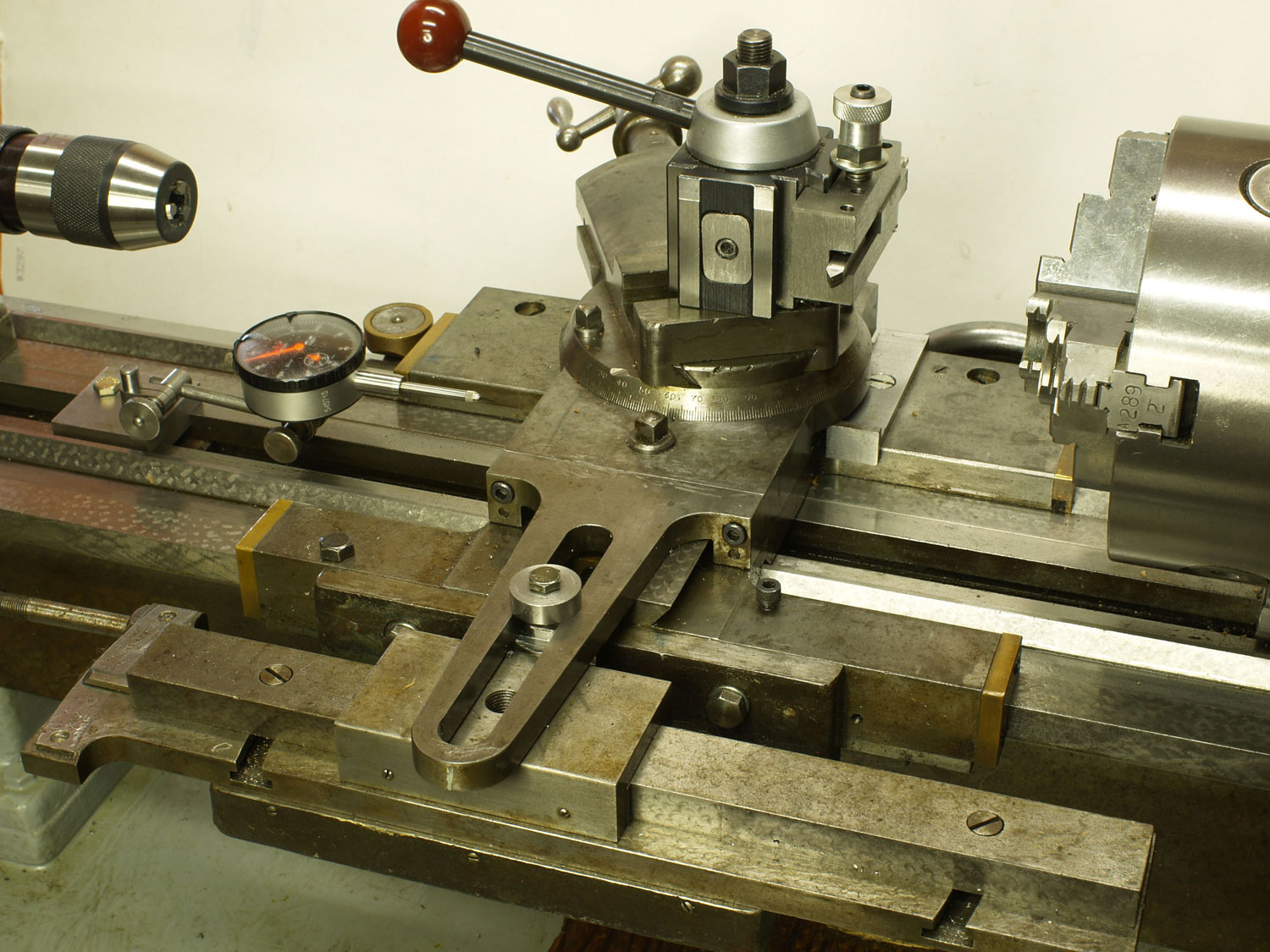
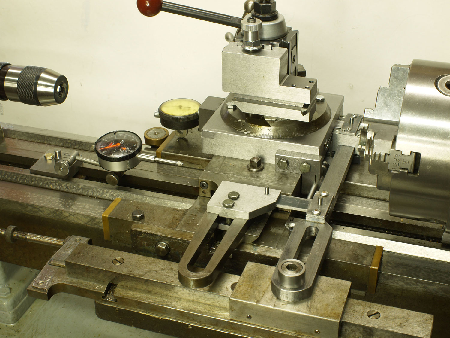
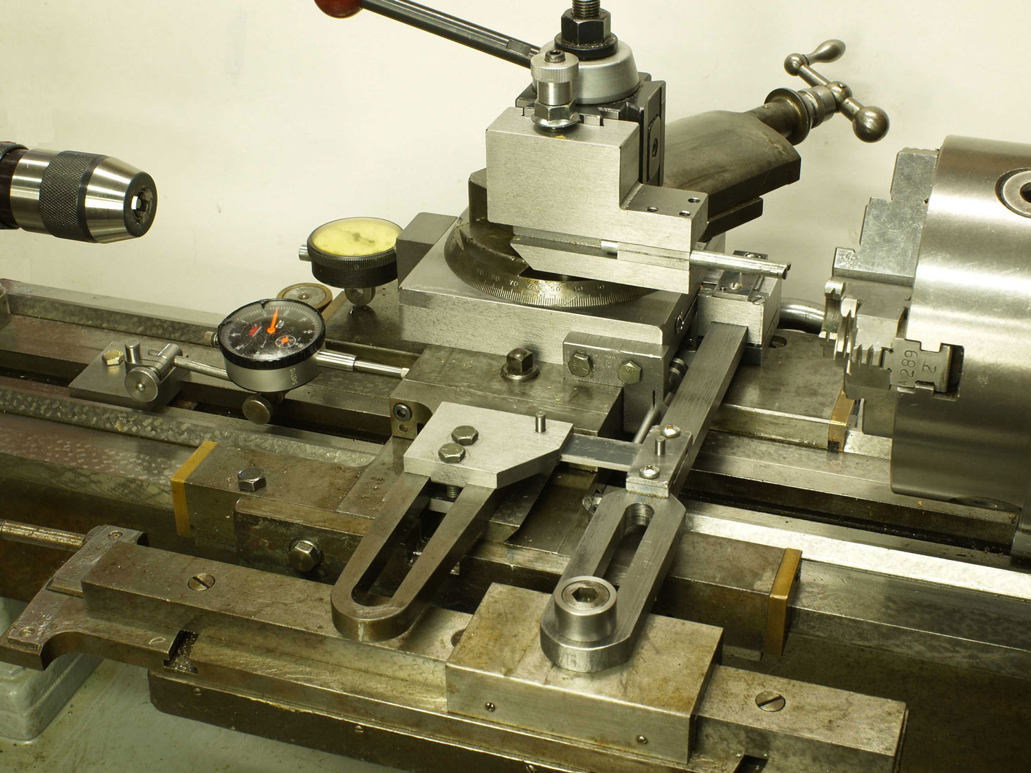
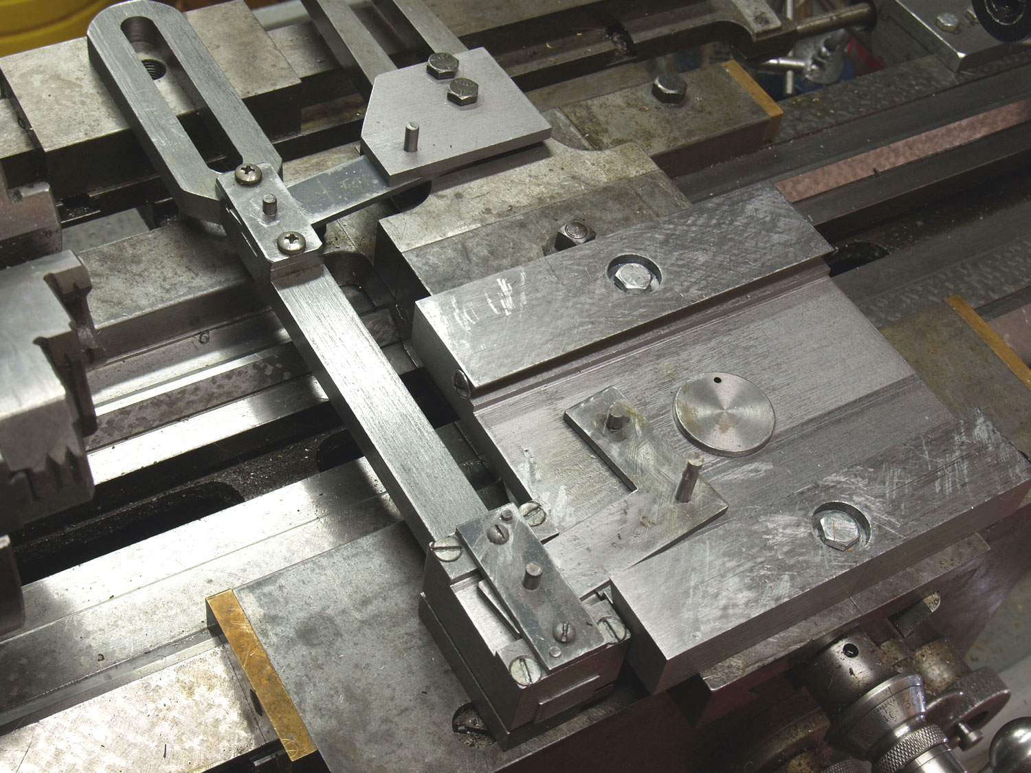
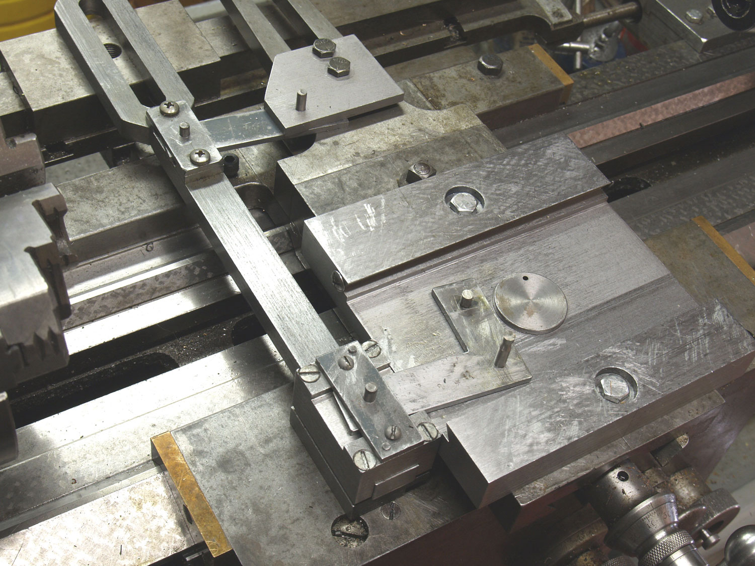
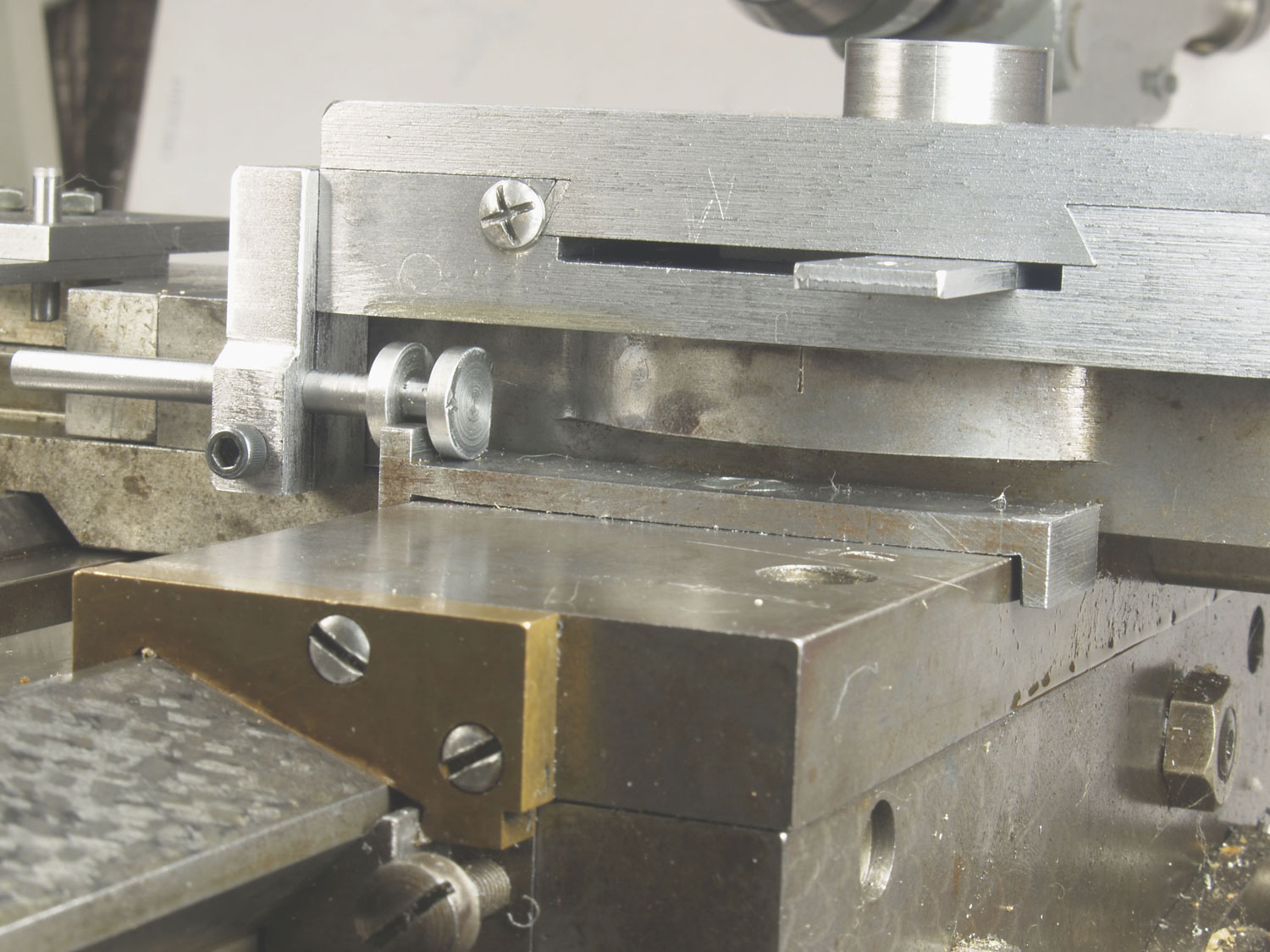
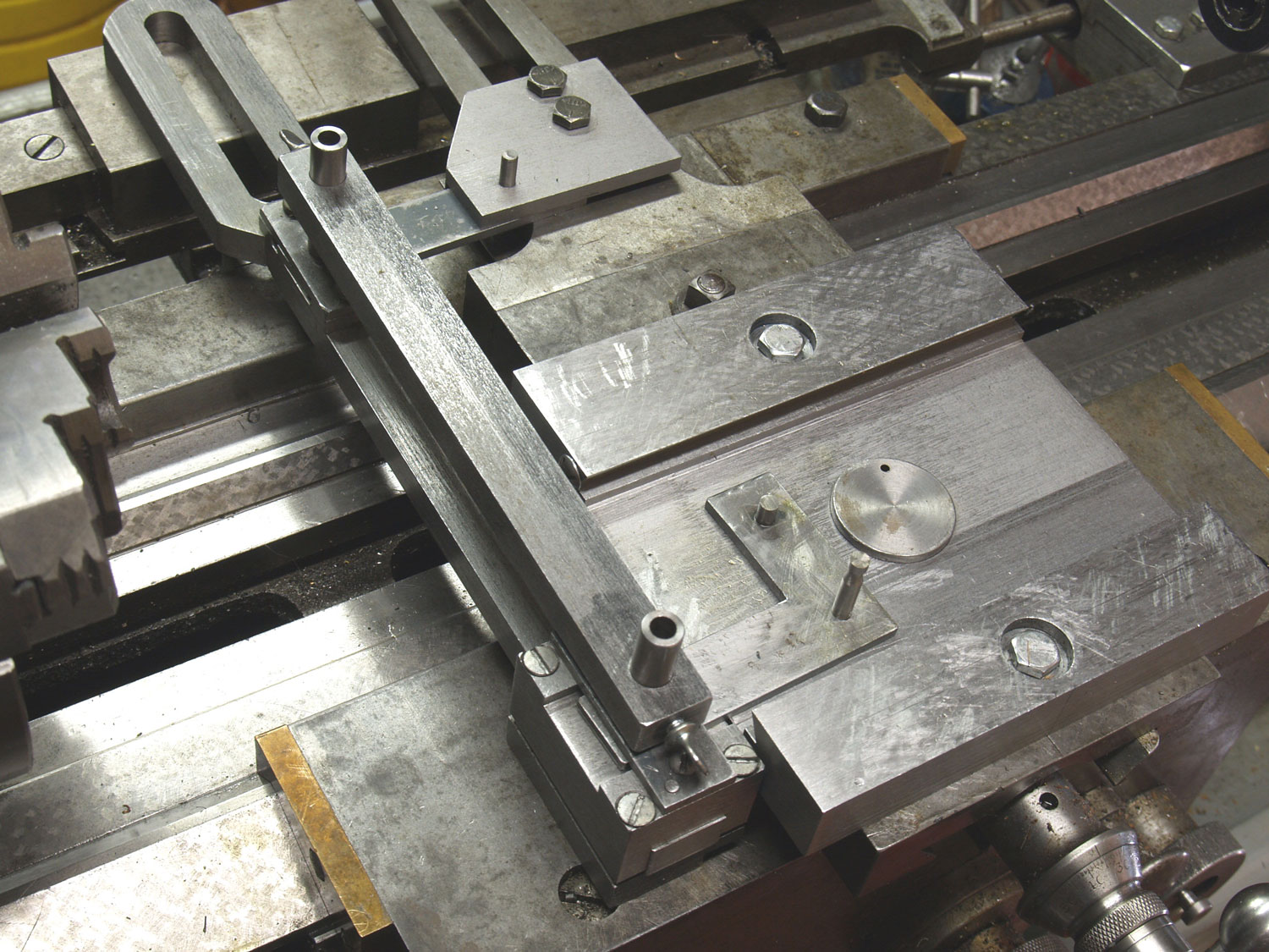
McDuffie added a dovetail slide between the carriage cross slide and the compound. The axis of this slide is parallel to the lathe bed. This added slide is actuated by a lever system so that the tool longitudinal travel is the travel of this small slide added to or subtracted from the carriage travel provided by the threading lead screw. This added travel must be directly proportional to the amount of carriage travel if the lead of the thread being cut is to remain constant. The issue of linearity of the movement will be dealt with at the end of this article, along with a test for linearity. The lever system drive I made for the short slide is best understood from examining photographs of the attachment I made for the Wade lathe. Figure 2 shows a setup for conventional outside diameter threading without the attachment. The view is from the back side so it can be compared with Figures 3 and 4 with the adjustable lead attachment engaged by a four-bar linkage clamped to the slider of the taper attachment for outside diameter and inside diameter threading. The lever system is on the headstock side of the carriage in order to have adequate room for the tailstock to support the work being threaded. Interference of the long link with the chuck is now an issue. So the length of the short arms was minimized while still providing about 1/8” travel of the short slide when the taper attachment is set at its maximum angle of 10 degrees. The short slide adds almost an inch to the height of the compound. An offset tool holder was made to accommodate this added height and is described in more detail later. The compound and top of the short slide were removed to show the four-bar linkage in Figures 5 and 6. The long link bar was disconnected from the taper attachment slider and moved forward and backward to show how an “L” shaped lever, pinned with the longer dowel pin to the lower half of the slide, rotates so that the short dowel pin on the other end moves approximately longitudinally. This short pin engages with a gray cast iron slider fitting into a transverse slot in the underside of the upper half of the slide. The top half of the short slide was inverted and laid on the lower half to show the slider in the slot cut with an end mill in Figure 7. The sides of the slot and mating slider were precision fitted with a small scraper.
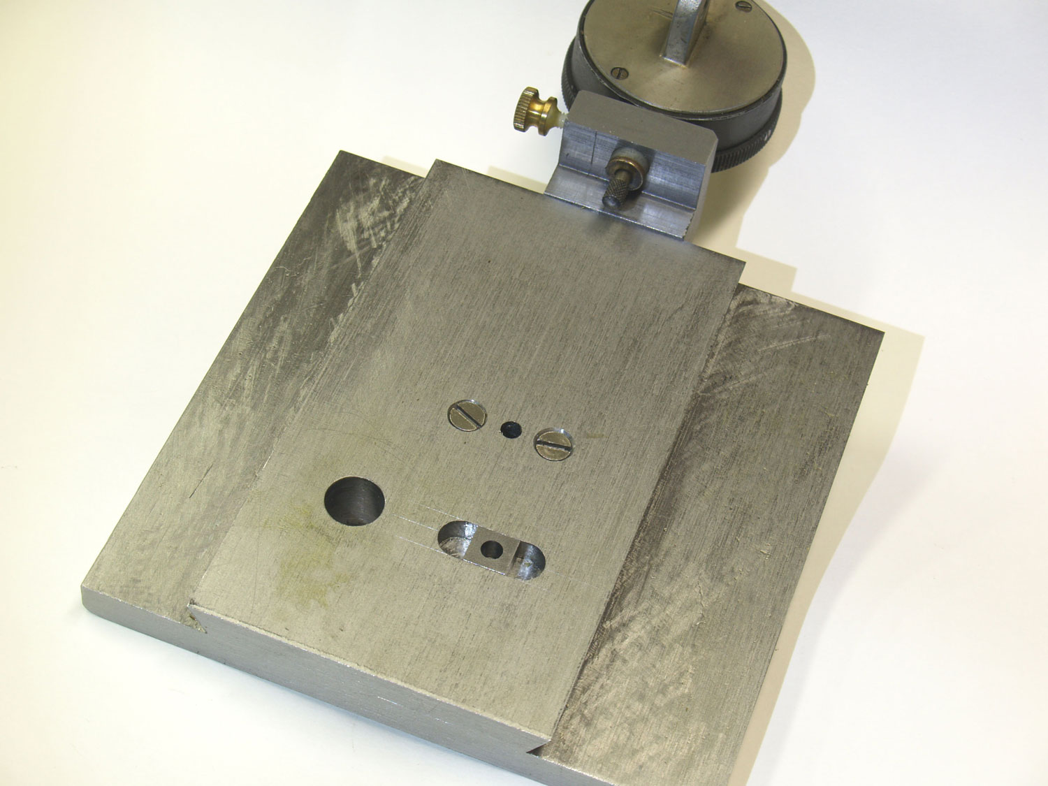
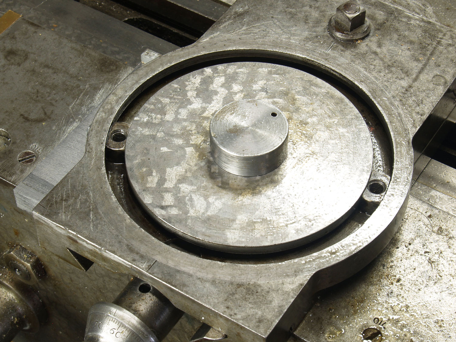
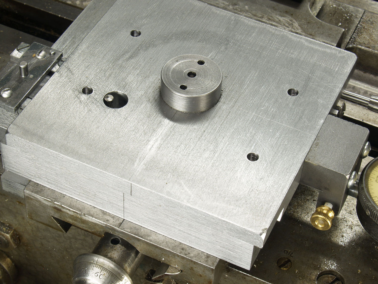
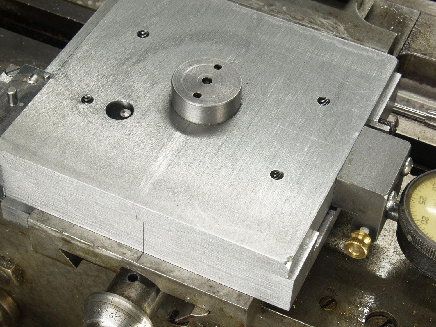
The top of the Wade cross slide, shown in Figure 8, has a cylindrical center post and a groove for “T” nuts that locate and attach the compound to the cross slide. This method of attachment differs from the Myford lathe of McDuffie, which has a rotary dovetail post clamped by transverse screws. I chose to assemble the lower half of the slide to the cross slide with bolts followed by installing the upper half of the slide with the “L” shaped arm with the slider engaged in the slot. Since the travel of the short slide will be a maximum of 1/8” in either direction, a long dowel pin passes through a 1/2” diameter clearance hole through the top of the slider and through the “L” shaped lever into the lower half of the slide. The hardened dowel pin was sized for a close push fit in the reamed holes of the lever and lower half of the slide by stoning with the pin rotating in a drill chuck. The upper part of this hardened dowel pin has a rough ground groove so it can be easily grabbed with a needle-nosed pliers for later removal. A tapered end pin is used to quickly align the hole in the lever with the hole in the lower half of the slide. The pin through the half-inch clearance hole is shown at the limits of slide travel in Figures 9 and 10. The use of a tapered gib, made from gray cast iron, permits easy assembly of the short slide. The thicker end of the gib with a mating wide screw head is visible on the upper right corner of the slide in Figures 10 and 11. A series of tapped holes is visible in the top of the slide, shown in Figure 12: these allow the compound to be mounted at a 29-30 degree angle for threading. Figures 9 and 10 also show scribed lines on the bottom side of the slide for alignment with the cross slide and to indicate the amount of travel from the centered position with the shorter leg of the “L” lever arm square to the longitudinal axis.
The long lever was removed to show details of the slide from the headstock side in Figure 11. Note that the outer portions of the dovetail are load bearing with a close fitting slot containing the “L” shaped lever. The thin end of the tapered gib can be seen on the left side. The end of the gib was trimmed to be flush with the end of the top half of the slide, and located by the head of a screw. The shaper cut load bearing surfaces of the slide were hand scraped for a precision fit and fine finish. This method was also relied upon by Henry Maudslay to make precision lathes. The slide moves with slight effort and no perception of roughness. Ted McDuffie relied upon lapping to improve the finish on his milled slide surfaces. Rubbing the mating surfaces together with abrasive, unlike properly done hand scraping, will not correct the form errors. I chose to make the slide from hot rolled steel to avoid warping expected if cold rolled steel, with its locked-in residual stress gradients, had been used. I would not consider using aluminum for the slide because of the poor compatibility of aluminum rubbing on aluminum as a wear couple.
The adjustable stop I had for the cross slide can not be used with the threading attachment. I find that such a stop is very desirable for threading because a dial setting does not have to be watched between threading passes when the tool is backed from the cut and returned to the same setting. A new stop was added which bolts to the lower half of the short slide as shown also in Figure 11.
It is very important that the opposite links of the drive system have the same length so that the opposite links remain parallel when the end of the long link is clamped to the slider of the taper turning attachment that actuates this linkage as the carriage moves (Figure 12). The short link and the corresponding segment of the “L” shaped lever have a pin hole spacing of 2.250″. A gauge was made to set the adjustable ends of the long lengths exactly the same. The exposed ends of the dowel pin pivots fit reamed holes in bushings clamped into the gauge bar as shown in Figures 13 and 14. Having access to the long pin in the lower half of the slide through the clearance hole in the upper half of the slide is an aid to easy use of the gauge. The thumbscrews allow the bushings to be set to allow for the different heights of the pivots, which are not on the same plane.
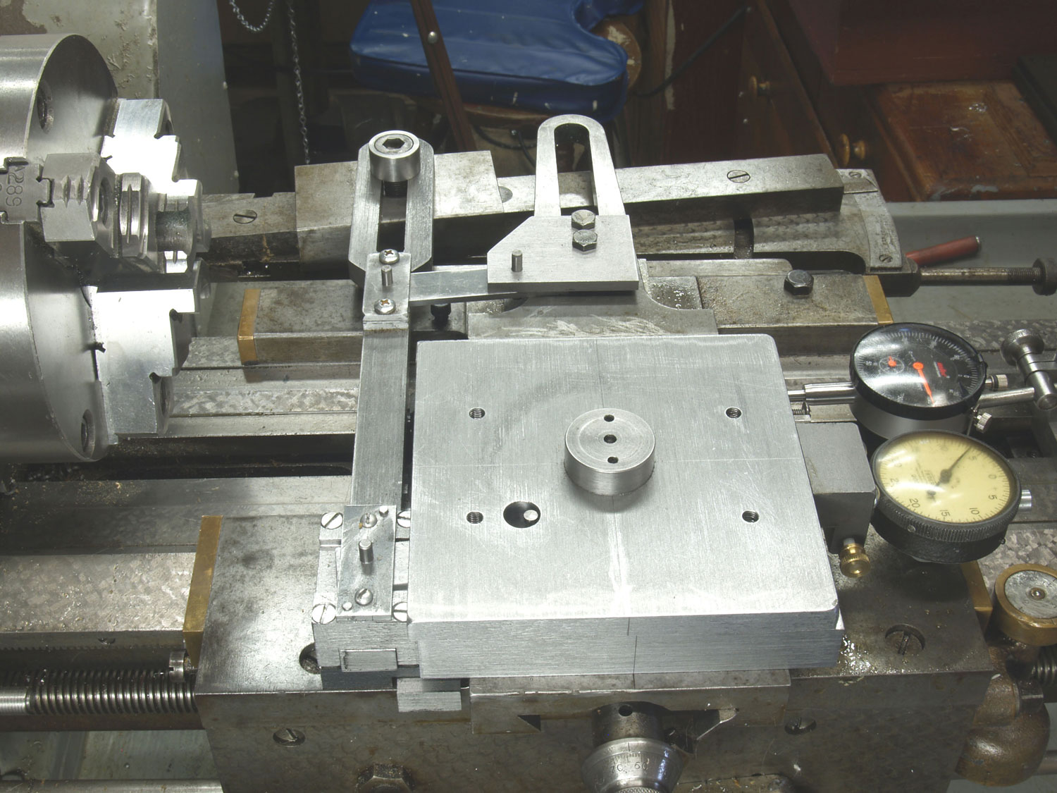

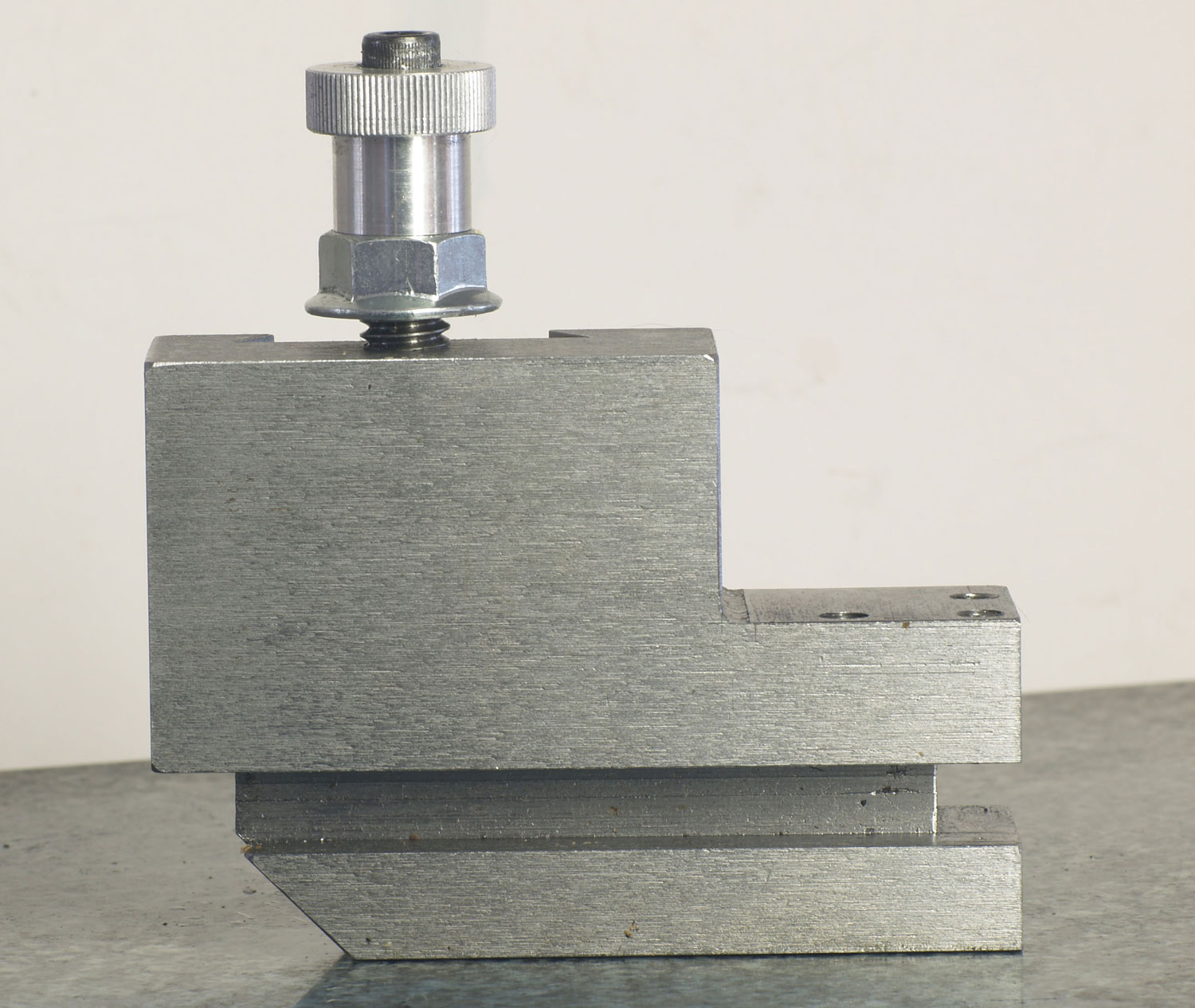
I use the Phase II tool holder system on the Wade lathe. The added height from the short slide required fabricating the offset tool holder shown in Figures 15 and 16. It was made from 1.25″ thick hot rolled steel. The tool holder clears the top of the male dovetail of the Wade compound. So the full travel of the compound is available to suit the diameter being threaded. Ted McDuffie also had to make a special offset tool holder for use with his attachment for the Myford lathe. Figure 17 shows the lathe from the front side set for internal threading with the new attachment and tool holder. The two dial indicators are for calibration of the thread lead adjustment provided by the short slide. The dial indicator at the rear measures the carriage movement; it is not normally needed, but is shown because it was used to check the linearity of the threading lead adjustment provided by the threading attachment. A 1″ gauge block was used to verify that this dial indicator was properly aligned. In normal application of the threading attachment, this dial indicator would not be present because a 1″ gauge block would be used to set this distance between the carriage and the carriage stop. The dial indicator attached to the top half of the short slide, shown in Figure 19, would be used to measure the amount of tool travel adjustment provided by this slide when the carriage is moved to the previously set stop. The angle setting for the taper attachment would be adjusted until the needed adjustment was obtained with 1.000″ travel of the carriage. The components of the adjustable thread lead attachment are shown in Figure 20.


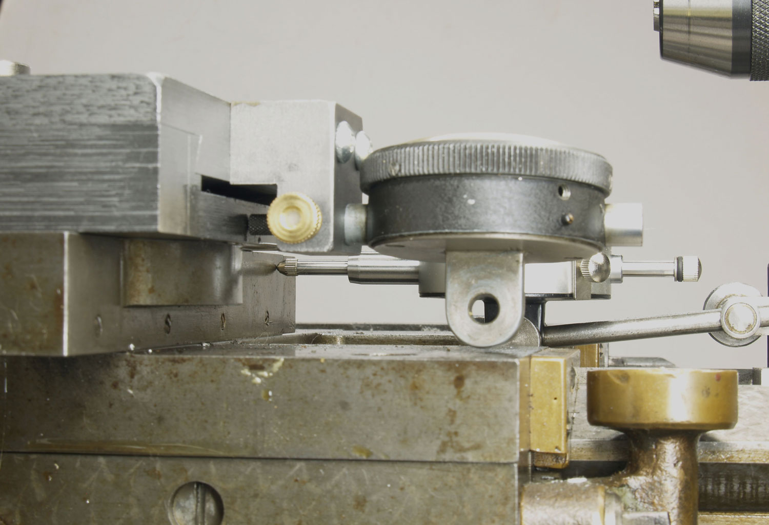


I have not yet used the adjustable thread lead attachment for threading, but I have tested the linearity of the adjustment using the method mentioned in the previous paragraph. The alignment of the scribed lines indicates when the linkage is square. The nonlinearity is expected to be maximum the farthest the short slide is extended from the square position. The travel of the short slide was measured with a dial indicator having 0.115″ travel and 0.0005″ divisions. My initial results were plotted on graph paper with one division per 0.001″ of short slide travel. I learned from this initial test that I could not trust the first 0.015″ travel of the 0.115″ travel. Only the final 0.100″ of its travel range was used for a second test. The taper attachment was set at its maximum of 10 degrees and the short slide was initially at the square position. The graph of the results taken at 0.050″ increments of carriage travel was quite linear over the 1.00″ with 0.097″ of short slide travel. The calculated error due to nonlinearity is 0.0007″ for the test conditions.
Comments
add comment