Combining Circular Oblique and Oblique Illumination to Enhance Detail and Contrast in Light Microscopy, Part I
Abstract
Enhancing detail and contrast in transparent specimens has always been a primary interest of microscopists. To such ends, several optical techniques have been developed, such as oblique illumination, circular oblique lighting (COL), phase contrast, differential interference contrast (DIC), and various similar techniques. What is presented in this article is a unique combination and application of COL, oblique illumination, and polarized light. In addition, stop shape and the addition of wave plates are also discussed.
Introduction
Although COL and oblique illumination are some of the oldest variations on brightfield microscopy, they are still powerful tools for improved contrast and enhancing detail. As a focus of research, both COL and oblique illumination, and variants, have been extensively studied and written about by many authors over the years. The purpose of this article is to discuss variations and combinations of these techniques that may not have been evaluated in the past with advantages and disadvantages of such.
The interest in COL and oblique illumination, with respect to this paper, stems from a desire to reproduce DIC-like images at a lower cost. It is well known that COL and oblique illumination can enhance contrast, and therefore the ability to highlight structures not easily visible under brightfield. A discussion and comparison of these techniques is given by Ted Clarke (2004). One of his key observations is that while both COL and oblique enhance contrast, oblique appears to give only “directional” resolution (dependent on orientation of sample and oblique mask). This is in comparison to COL in which resolution is not directional. The observed resolution enhancement of both techniques is consistent with Abbe’s theory with respect to increasing the order of diffraction maxima entering the objective and thus improving resolution (Anon., 2005).
In summary, both COL and oblique have advantages and disadvantages. The advantages of COL, in comparison to oblique illumination, are that the enhancement of resolution is slightly better, non directional, and has little impact on light intensity. On the negative side, there is no good way to control illumination with COL especially if high wattage light sources are used. This is because the COL setup requires that the condenser and field iris remain fully open or resolution enhancement is lost. An advantage of oblique illumination is directional contrast which results in subjects taking on a 3D appearance. Unfortunately this 3D effect is gained at the loss of light intensity.
The use of polarized light in combination with COL termed “Polar Annular Lighting” has been studied by Oku (2009) and, as illustrated, is capable of excellent resolution with respect to diatoms.
A study was undertaken to design a stop and filter system containing elements of the above mentioned systems which could overcome some of the drawbacks of each while preserving the optical benefits of both.
Materials
Experiments were conducted using a Zeiss GFL microscope equipped with a Zeiss 1.4 NA Achr/Apl condenser and intermediate tube beam splitter. Light was supplied by a 6v 15 watt bulb with tungsten filament. Objectives were either a Zeiss 40X 0.65 NA Plan Achromat (0.17), or Nikon CF 60X 0.85 NA (0.11-0.23) dry objective with cover slip correction collar. The camera utilized was a Moticam 2300 equipped with a Zeiss KPL 10X eyepiece and a Moticam 16 mm intermediate lens. One photo utilized a Nikon CF 10X Photo eyepiece which is noted in the caption. The specimens are from an 8 form diatom test slide by Klaus Kemp. Opaque masks were cut from black electrical tape and mounted on 1¼ inch (31.75 mm) standard glass filters. The circular polarizing film, ¼ wave plate film, and polyester film (used for the repair of automobile windshields) were all cut into 32 mm diameter round filters using a commercial gasket cutter. Circular polarizers were cut from commercially available film, and arranged so that they produce a black background when crossed (crossed Nicols).
Method
The crescent mask for prototype 1 was cut with a 40 mm diameter punch and the ellipse cut with a 42 mm diameter punch. The width of the ellipse is approximately 7 mm at the center, and the length is 24 mm. The ellipse is placed in the absolute center of the 1¼ inch (31.75 mm) inch glass filter slightly overlapping the crescent oblique mask (see Figure 3). The COL stop for prototypes 2 and 3 is a 10 mm in diameter circle, centered in the plain glass 1¼ inch (31.75 mm) filter. The crescent mask for prototype 2 was cut with a 32 mm diameter punch. The polyester film filter and plastic wave plates are 32 mm in diameter. One polarizing filter is placed in the microscope nosepiece (just under the head and above the objective). The other portions of the filter assembly are placed over the field diaphragm on the base of the GFL microscope, i.e., the light exit port. Images were converted to black-and-white via desaturation based on luminescence using the shareware program GIMPshop.
Optical setup sequence:
- Focus on specimen
- Open field diaphragm and condenser iris fully
- Cross polarizers so that the background is black; this can be adjusted to off cross if desired. In most cases the polarized filters have been crossed unless otherwise noted.
- Insert special filter
- Focus condenser up or down until the observed image of the specimen is just free from a quasi “phase” effect. There may be some slight darkness on the edge of the field of view. A phase telescope can be used to center and focus the special filter in the objective back focal plane.
- Rotate the special filter with the polyester film sheet until a portion of the background is bright green.
- Insert ¼ wave plate and rotate it until background becomes bright. This can also be used to adjust brightness since the field and condenser irises must remain in the fully open position.
Development and Results
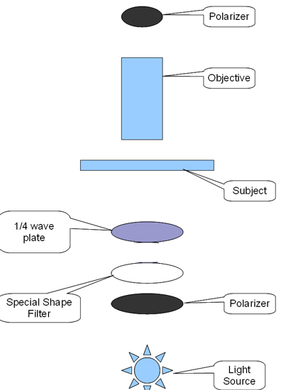
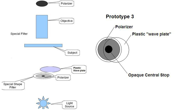
A simplified schematic of the general setup utilized is illustrated in Figure 1. Absent from the image is the condenser, field iris, and field lens. In order to simplify the image, these items have been intentionally left out.
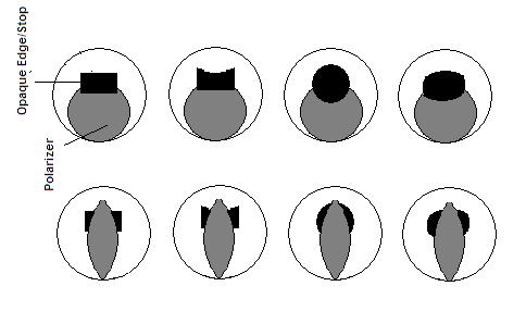
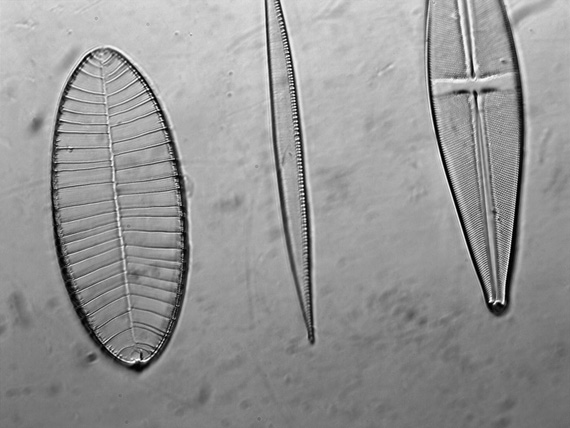
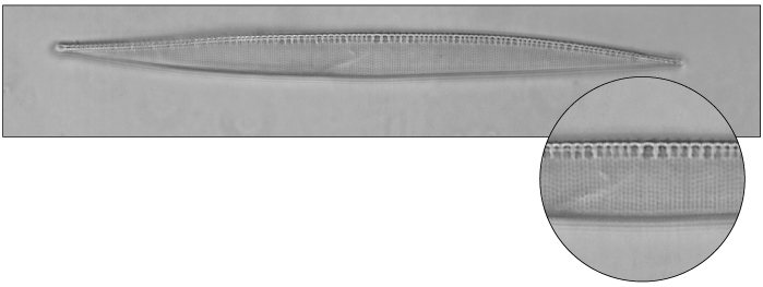
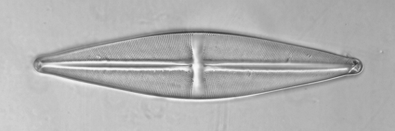
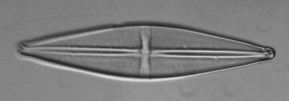
An eight-form diatom test slide by Klaus Kemp was selected as the test subject. Nitzschia sigma and Stauroneis phoenocenteron were utilized for assessment of resolution based on the fact that these diatoms have known striae spacing of approximately 435 nm and 714 nm respectively (University of Texas, 2004). Numerous “special filter” designs were constructed and tested: these are illustrated in Figure 2. These early designs incorporated both an opaque mask for the center stop, and a polarized portion for additional contrast. These initial masks, while improving contrast, did not drastically improve the image. It was also found that the best image was obtained then the filter was rotated such that the polarized portion became opaque, completely blocking the light. It was therefore decided that certain components of these early designs would be retained (such as the elliptical center stop), but the materials changed and other shapes were introduced.
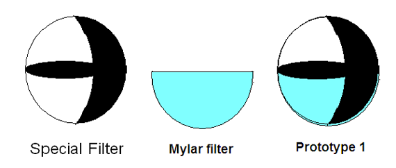
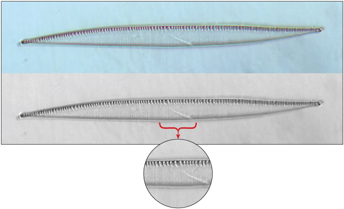
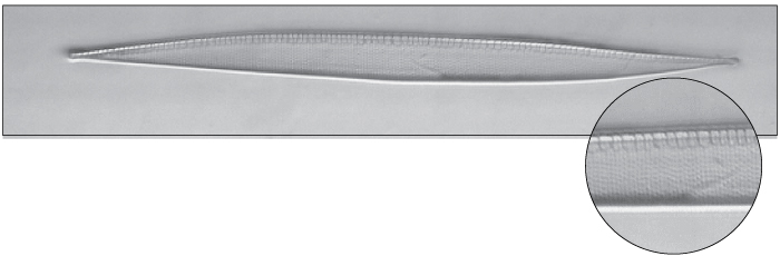
It also became evident that in order to produce the desired 3D effect there would need to be included a crescent-shape mask. These are classically used to produce oblique illumination, but often they are placed so that the majority of the direct light is blocked. It was decided to move the mask back, more toward the edge, and include an elliptical center stop. These changes led to the development of the mask seen in Figure 3. Noting that many crystalline and semi-crystalline materials have very low retardation and birefringence, it was decided that an attempt would be made to augment the filter with a thin semi-circular piece of polyester film. It is believed that the polyester film semi-circle shaped filter serves the purpose of retarding a portion of the light by a certain wavelength thus resulting in the sample being illuminated by two light beams of differing retardation. This combined with the center stop and semi-circular oblique mask results in detail enhancement. This filter setup will be referred to as prototype 1. Image results are shown in Figures 4, 5, and 6. Figure 5 was taken with the same filter setup as Figure 4, except that the polarizer and analyzer were not crossed as noted in the photo caption.

While the resolution is good and 3D effect is present, the resolution appears to be directional and related to the orientation of the elliptical center stop. This is compared to a simple COL stop (shown in Figure 7).
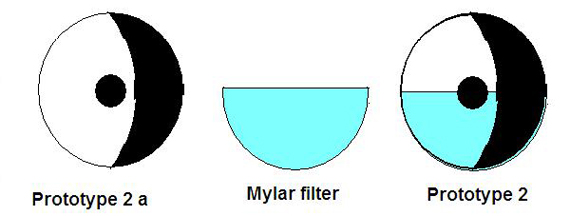
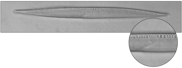
Based on the above results the stop was again modified, with removal of the center elliptical stop and substitution of that with a round centered stop. This will be referred to as prototype 2. A slight variant on this design without the polyester film sheet was also evaluated; this will be referred to as prototype 2a. A schematic of each design is shown in Figure 8, image results are shown in Figures 9, 10, and 11.
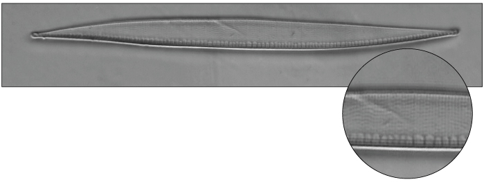
The last modification that has been studied thus far is shown in Figure 12. This setup is slightly different than the general setup shown in Figure 1. The main points of difference between the general setup and this modification are the absence of a polyester film sheet and opaque mask. There is no true oblique mask with prototype 3: rather, the oblique effect is provided by the crossed polar filters and the plastic wave plate. The crescent shaped area remains dark (by the crossed polar filters), while the area under the wave plate is altered into a bright region. This filter arrangement is referred to as prototype 3. Diatom test images utilizing the prototype 3 setup are shown in Figures 13 and 14.
Discussion
Prototype 1
Although the prototype 1 setup provided enhanced resolution and thus better image quality over brightfield, the observed enhancement provided only directional resolution benefits. Depending on the orientation of the subject or elliptical mask, certain features of the test diatoms could be seen or not seen. This directional resolution is definitely not preferred and was inferior to the resolution observed with a simple COL setup. The shadowing is also directional. Prototype 1 did impart an acceptable 3D aspect to the image and with the inclusion of the ¼ wave plate filter it is possible to control specimen illumination. Although not shown in this paper, the inclusion of the polyester film filter did seem to improve the contrast and thus aid in image quality with prototype 1.
Prototype 2 and 2a
It is clear from examination of Figures 7 and 9 that prototype 2 provides resolution improvements on a par with the simple COL setup (if not slightly better). In addition, there is a distinctly 3D aspect to the images. As in the case of prototype 1, this 3D effect is a direct result of the elliptical oblique stop utilized in the design, is directional, and depends on the position of the crescent-shaped mask. It is also clear from an examination of Figures 9 and 10 that the inclusion of the semi-circular polyester film filter has improved contrast. It is believed that this may result from illuminating the sample with light of two different retardations, the differential retardation being a result of the added retardation provided by the polyester film filter. Again, as in the case of prototype 1 with the inclusion of the ¼ wave plate filter, it is possible to control sample illumination.
Prototype 3
Prototype 3 represents a change in both filter setup and optical train. Images produced via this prototype have very good resolution, comparable to that obtained via COL and via prototype 2. Resolution enhancement is also not directional, although the shadowing effect is. As in the design shown as prototype 2, prototype 3 also has the potential to illuminate the sample with light retarded to different degrees. By partially crossing the polar filters and rotating the clear plastic wave plate, it is possible to control the shadowing and sample illumination (although not quite as simple as with prototypes 1 or 2).
Conclusions
While all prototypes offer some improvement in contrast, resolution, and shadowing over brightfield, the resolution improvement provided by prototype 1 is directional, and thus, depends on sample and filter orientation. Prototypes utilizing a centered round stop give non-directional resolution improvement: this, combined with an oblique crescent-shape (either as an opaque mask or as a cross polar darkfield), adds the desired 3D effect to the images at a very small cost of light intensity. The optical train illustrated also allows for the adjustment of light intensity which is not possible with the normal COL or oblique setup. Finally the inclusion of a polyester film half circle appears to further enhance contrast as seen in comparing images taken with prototypes 2 and 2a. It is clear that a simple design, such as prototype 2 or prototype 3, can offer the microscopist on a budget image quality and an overall appearance similar to those obtained via DIC at a cost of around $20.00 (USD). With some additional experimentation, either of these systems (prototypes 2 or 3) could be adapted to any microscope, or, conversely incorporated into a condenser.
Cited References
Clarke, T. (2004) Evaluation of a Prototype BF-DF-Oblique-Circular Oblique Lighting (BF-DF-Obl-COL) Condenser. Retrieved September 28, 2011, from www.modernmicroscopy.com:
http://www.modernmicroscopy.com/main.asp?article=53
Anon. (2005) Innovation 15, Carl Zeiss AG, 2005 “From the History of Microscopy: Abbe’s Diffraction Trials”. Retrieved September 29, 2001, from http://www.zeiss.com/C125716F004E0776/0/D1B2BF1284180E37C125717C003EDF5A/$File/Innovation_15_18.pdf
Oku, O. (2009) Mic-UK. Retrieved September 29, 2011, from Microscopy UK: http://www.microscopy-uk.org.uk/mag/indexmag.html?http://www.microscopy-uk.org.uk/mag/artjun09/oo-diatom.html
University of Texas (2004) Bio 205 lab PDFs Diatoms. Retrieved September 28, 2011, from University of Texas EDU: http://www.sbs.utexas.edu/bio205l/lab_pdfs/diatoms.pdf
Contact the Author:
William Mark Ph.D.
Director Product Design
Pfizer Consumer Healthcare
William Mark
Comments
add comment