Hand-Sectioning and Identification of Pressure-Sensitive Tapes
Introduction
Pressure-sensitive adhesive tapes are encountered in criminal investigations as evidence from a crime scene, in document examinations as residues or contaminants on the documents in question, and as contaminants in food, pharmaceutical, and other consumer products. In these cases, it is necessary to be able to identify the type and possible source of the tape in question, often from a very small sample. In addition, certain sampling techniques, such as dust sampling, require the use of adhesive tapes to lift samples of particles from a solid substrate. The analyst must then choose a suitable solvent to remove the adhesive from the particles of interest, which requires some knowledge about the kind of tape that was used and its solubility properties.
A reliable method has been developed for preparing cross-sections from tape samples as small as 1 mm2, which can then be photographed, analyzed by any suitable means, and compared to known reference samples. The method involves immersing the sample briefly in liquid nitrogen, and cutting cross-sections by hand while the sample is still partially frozen. The advantage of this method is that the resulting specimen will maintain its original cross-sectional dimensions, without any dragging or deformation of the tape layers. Cross-sections that are prepared by this method are also much thinner than those prepared at room temperature, on the order of 10-50 μm compared to 100-200 μm for room temperature preparations.
Description of Method
For all of the steps in this procedure, the slides are placed on top of a glass block that measures 3 x 1 x 1/2″, which elevates the slide so that one can easily work at hand-level. The glass blocks are described in detail in The Microscope Vol 50:4, pp.159-168 (2002).
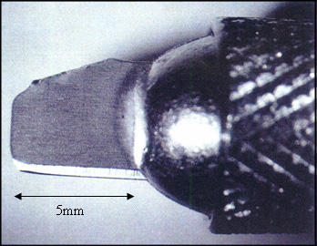
The choice of cutting blade will greatly affect the quality of the finished cross-sections. A good blade should be sharp, thin, and stiff, with a cutting edge parallel to its length. Micro-surgical blades are thin and sharp, but they bend at the tip, and their cutting edge, 15 and 45 degrees from horizontal, makes these blades hard to position for sectioning. Double-edged generic razor blades have all of the desired qualities. Four cutting blades can be prepared from one double-edge razor blade with a pair of heavy-duty scissors, as shown in Figure 1a. Each blade will fit into an X-Acto knife holder, and should be oriented so that the curved corner of the blade is used for cutting. The blade should not protrude more than 5 mm from the holder (see Figure 1b), or the blade will bend too easily. Note that the blades are fragile. The cutting tip, less than 1 μm, must be handled gently, and after a few cuts the blade should be replaced with a fresh one. To check if a blade is still sharp, turn it upside down and focus on the cutting edge at about 20X magnification under a stereomicroscope. A bright line, no matter how fine, indicates that the cutting edge of the blade has been bent. An undamaged cutting edge is difficult to see at 20X magnification.

Step 1 – The Preparation Slide
The preparation slide allows the analyst to cut a 1.5 mm-wide strip of the subject tape, anchor it, and transfer it to the sectioning slide for Step 2. The preparation slide is a standard glass microscope slide to which a 2” long strip of double-sided tape has been attached (See Figure 2). At one end of the slide, a stack of tape squares (Scotch Magic™ Tape #810), about 1/2″ x 1/2″ and about 15 layers thick, is placed adhesive side up. The stack of tape squares is made by slicing a block of tape from the roll, and cutting a beveled edge at one corner of the stack so that it is easy to pick up one layer of tape at a time. If the subject sample consists of double-sided tape, you will also need a stack of about 50 plastic wrap squares, about 1/4″ x 1/4″, next to the Magic™ Tape Squares. For the plastic wrap squares, we found that generic wrap purchased from Jewel Food Stores worked best; Saran Wrap™ was too oily and did not adhere well to the subject tape samples.
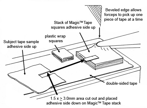
A small piece of the subject tape, about 1.5 x ≥3.0 mm in size, is placed adhesive side down on the stack of Magic™ Tape squares, so that one third of the subject tape extends off of the Magic™ Tape stack, as shown in Figure 2. If the subject sample consists of double-sided tape, a square of plastic wrap is removed from the stack and placed on top of the subject tape. The top layer of the Magic™ Tape squares, with the subject tape attached, is peeled from the Magic™ Tape stack and transferred to the Sectioning Slide.
Step 2 – The Sectioning Slide and Cross-Sectioning Process
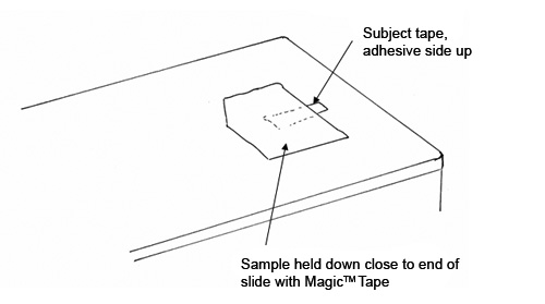
The Sectioning Slide consists of a plastic Permanox® cell culture slide (See Figure 3). We recommend a plastic slide instead of glass for this step for two reasons. First, the plastic will not damage your blade while cutting the sample. Second, plastic is a good thermal insulator and will allow you to hold one end of the slide with your fingers while dipping the other end into the liquid nitrogen. The Magic™ Tape is placed, adhesive side down, at one end of the Sectioning Slide. In this orientation, the subject tape is lying with the adhesive side up.
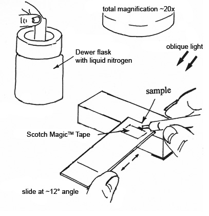
Prior to cutting the sample, place the slide under the microscope and tilt the end of the plastic slide that holds the sample up on a glass block, while looking at the sample at about 20X magnification (See Figure 4). Move the slide back and forth slightly under the microscope until the sample is in focus, and note the position of the slide at this point—you will need to return the slide to approximately this position after freezing the sample. Dip the end of the slide that is holding the sample into a small dewar of liquid nitrogen, and hold in the nitrogen for 1-2 seconds. Remove the slide from the liquid nitrogen and quickly replace it under the microscope in the same approximate position that you noted earlier. Move the slide back and forth quickly to bring the sample into focus (Because the analyst is holding the slide with one hand and the cutting blade with the other, there is no free hand for turning the focus knob of the microscope). The subject tape should be ready to section in less than 2 seconds, however the time will vary for each tape sample. In some cases, the adhesive will be ready to cut, but the backing will still be too brittle. Most samples are ready to cut as soon as the ice crystals that have formed on the surface of the sample start to collapse. The soft plastic slide allows the analyst to position the tip of the cutting blade before slicing the sample, and allows better control over the thickness of the cut sections. Slice across the sample with a sideways and downward motion, not a straight downward motion. If the cross-section clings to the plastic slide it must be discarded, since it will adhere to the slide as soon as it warms to room temperature. Only cross-sections that cling to the cutting blade are transferred to the examination slide in Step 3.
The sample slide must be dipped in liquid nitrogen again prior to cutting another cross-section from the same subject sample. Note that if wider subject sample strips than the recommended 1.5 x ≥3.0 mm size were originally cut for the preparation slide, they would tend to separate from the Magic™ Tape more and more each time that the slide was dipped into liquid nitrogen, because the nitrogen migrates beneath the Magic™ Tape in places where the adhesive is not touching the plastic slide, and separates not only that area but the surrounding area as well.
Step 3 – The Examination Slide
The Examination Slide is a glass slide that is covered with a 2″ long piece of double-sided tape, 1/2″ wide, placed along one edge of the glass slide. This 2″ long piece is placed over shorter pieces of the same tape that have been oriented at 90° to the 2″ long piece. (See Figure 5) The two layers of tape, oriented at 90°, will cancel any interference from the birefringent polymer layer of the double-sided tape when examined by polarized light microscopy (The suggestion for canceling interference by this method was suggested by Jan Hinsch). The Examination Slide is elevated on two glass blocks, which places the slide at the ideal height so that the analyst can hold the cutting blade (with the attached cross-section) horizontally while gently touching the cross-section to the double-sided tape. The cross-section will adhere to the tape on the Examination Slide, and can be examined directly through the double-sided tape. This results in a good microscopical image, since the adhesive of the double-sided tape makes good contact with the cross-section, and acts like an immersion oil. Note that tape cross-sections cannot be examined in refractive index liquids or immersion oils, since the adhesives will swell and eventually separate from the backing.

Analysis of Tape Cross-Sections
Depending on the purpose of the analysis, any number of tests can be performed on the prepared cross-sections. The type of information that we have been collecting from the cross-sections includes: thickness and appearance of each layer, fluorescence at 365 nm (UV) and 400 nm (VIS), solubility in common solvents, and identification of each layer by infrared spectroscopy (micro-FTIR) and energy dispersive x-ray (EDS) spectroscopy if needed. We have found it helpful to use a data sheet to tabulate the information from each sample. The data sheet includes a photomicrograph of the cross-section taken at 200X magnification, on which each layer is numbered, starting from the outermost layer (farthest from the adhesive) as Layer 1. If a layer includes more than one species, such as adhesive and filler particles, these are labeled 1a, 1b, and so on. The data table includes the thickness of each layer in micrometers, an estimation of birefringence of the layer (low = 0-0.010, moderate = 0.010-0.050, high = >0.050), a notation about whether the layer fluoresces at each wavelength and if so, what color and intensity (weak, moderate, or strong). The analyst will then estimate the solubility of each layer in common solvents (soluble, swells, or insoluble), and make notes about the identification of each layer by IR and/or EDS, plus any other observations of interest. Our data sheets are stored in a binder, in individual plastic pouches, along with a sample of the original tape in case additional tests are needed in the future.

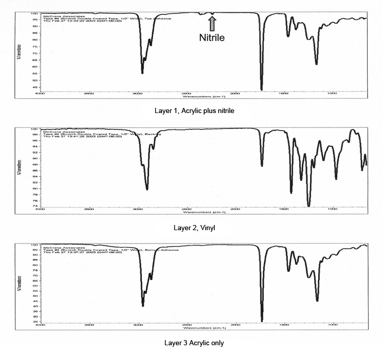
Figure 6 is a photomicrograph of double-sided tape, showing the quality of the cross-sections that can be obtained with this method. Note the parallel layers and smooth surfaces of the sample, which would be impossible to achieve with a room-temperature preparation. The bottom layer in the photo is the plastic wrap that was placed over the sample in Step 1; when plastic wrap is used in Step 1 it will remain with the cross-section through the entire process, as it cannot be removed without damaging the cross-section. The layers of this tape were thick enough that they could be manually separated for infrared analysis. Figure 7 contains infrared spectra of the three layers of the tape sample. Layers 1 and 3 were identified as acrylic adhesives, but the spectrum of Layer 3 displays a small nitrile band near 2240 cm-1 that is not present in Layer 1, allowing the two adhesive layers to be distinguished from each other.
A photomicrograph of a cross-section of duct tape is shown in Figure 8. The excellent quality of the cross-section allows one to clearly see the orientation of the reinforcing fibers, as well as the fine particles in the backing and adhesive layers.

A cross-section of the same tape is shown under the fluorescence microscope in Figure 9, and highlights the usefulness of the fluorescence examination. The backing of this particular tape is fluorescent, while other duct tapes may not be fluorescent or may fluoresce with a different color, which might allow this tape to be matched with possible suspect tapes in a criminal investigation.

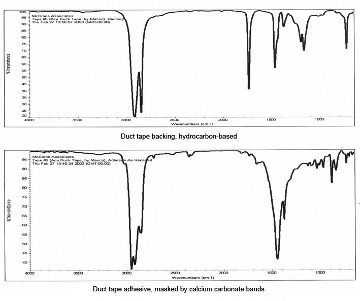
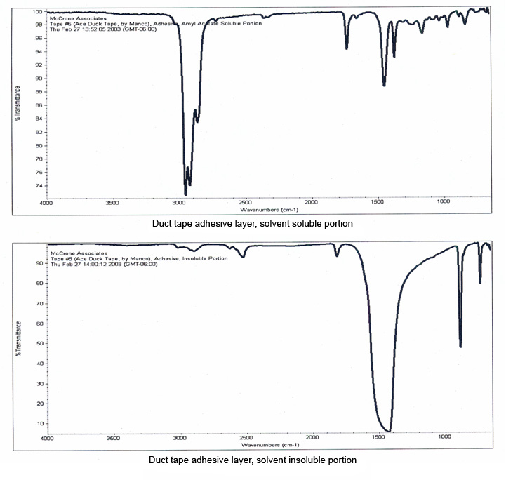
The layers of this tape were manually separated for infrared analysis, and the resulting spectra are shown in Figure 10. The backing was readily identified as a hydrocarbon-based polymer, but the spectrum of the adhesive was dominated by bands due to the calcium carbonate filler which masked the bands of the polymer. A small portion of the adhesive, about 100 μm in size, was extracted with micro-drops of amyl acetate, which separated the polymer from the inorganic filler.
Infrared spectra of the separated components of the adhesive (Figure 11) show that the polymer has been successfully isolated from the adhesive, and can be easily compared against possible source tapes.
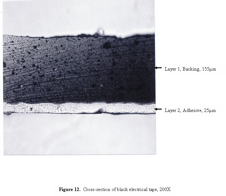
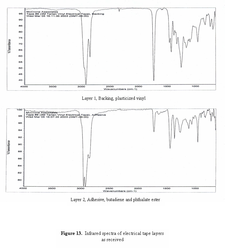
A photomicrograph of a cross-section of black electrical tape is shown in Figure 12. Even though the backing of the tape appears to be opaque, the cross-section is thin enough that light can be transmitted through the section, revealing the grainy, non-homogeneous consistency of the layers. Infrared spectra of the two layers are shown in Figure 13. The spectrum of the backing is consistent with plasticized vinyl, and the spectrum of the adhesive is dominated by bands due to butadiene and phthalate ester plasticizer.
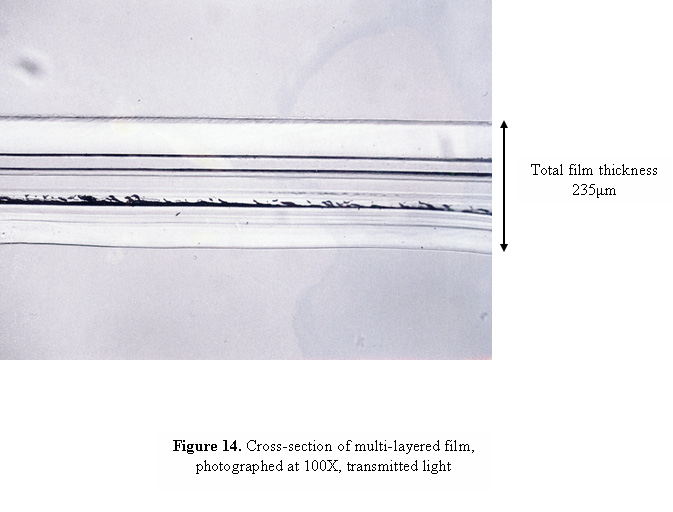
The more layers that are present in the tape, the thicker the cross-sections will have to be in order to avoid separation of the layers. As the sections become thicker, reflections can occur between adjacent layers which, when examined under the microscope, can give the appearance of multiple layers where only two layers are present. A similar optical illusion can also occur if the section was not cut exactly perpendicular to the tape, so that you are seeing the overlap region of two layers as an additional layer under the microscope. Figure 14 contains a cross-section of a multi-layered film that shows this effect. Although the film contains only 9 layers, the photograph appears to contain many more. In order to determine the actual number of layers present in the cross-section, we have found it useful to use a method called “double sectioning”, or cutting a cross-section from the cross-section. A portion of the cross-section, approximately 25 μm wide, is cut as shown in Figure 15, and pressed with a cover slip or glass wedge onto a glass slide or directly onto a KBr crystal for infrared analysis.

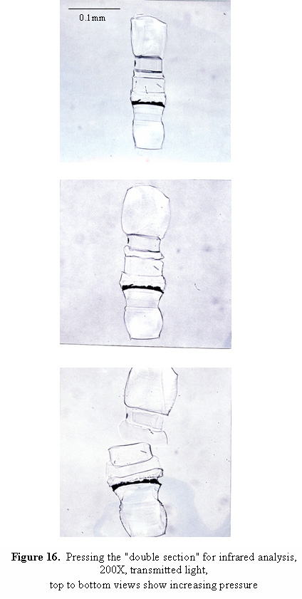
With increasing pressure, the layers of the tape will flatten and spread out to at least twice their original size, and finally will begin to separate from each other as shown in the sequence of photographs in Figure 16. The actual number of layers in the sample, and the relative hardness of each of the layers, will be apparent from the pressed sample. This method is useful for preparing samples for infrared analysis, since layers that are very thin will usually become large enough that good quality spectra can be obtained.
Discussion
The cross-sections that can be obtained by this method are much thinner than those prepared at room temperature, on the order of 10-50 μm vs. 100-200 μm for room temperature preparations. The cross-sections are of high quality, with smooth parallel edges, and reveal the fine structure of the individual tape layers. This method is especially useful for laboratories that do not have a cryo-microtome, since the quality of the cross-sections is similar to what can be obtained by cryo-microtomy. The ideal sample size for this method is about 10 mm2, although we have successfully prepared cross-sections from samples as small as 1 mm2, which would be too small for cryo-microtomy.
Because the sections are hand-cut, replicate sections of the same tape may show some variation in apparent thickness of the layers, depending on whether the sections were cut exactly perpendicular to the tape each time. If a more accurate measure of the layer thicknesses is required, we recommend cutting multiple cross-sections from the sample to determine the amount of variation from one section to another.
The hand-sectioning method has been found to be a reliable, quick, and relatively simple way to prepare cross-sections of good quality from adhesive tapes. However, the method does require that the analyst have some proficiency with manipulation of small particles under the microscope. Although the method looks somewhat complicated on paper, the entire procedure takes only a few minutes from start to finish once all of the materials are assembled around the analyst. The preparation slide can be used for about 15 samples, the sectioning slide should be changed after 5-10 samples, and the examination slide should be changed after 2-3 samples. These slides can be stored in a box on the microscope bench, along with a supply of razor blades. With practice, multiple sections can be obtained from a tape sample in less than 30 minutes.
This article was originally presented at the Pressure Sensitive Tape Council’s 2004 Global Technical Conference XXVII in Orlando, Florida.
Comments
add comment