Microanalysis of Craters in Organic Coating of Aluminum Cans
Abstract
In this article, we are going to discuss a case study in which we conducted an investigation to track down an elusive cratering problem involving the inside coating (IC) of aluminum cans, and discovered a surprising set of circumstances that led to a successful resolution of the problem.
In the autumn of 1994, a can manufacturing plant had a significant problem with cratering of the inside coating of aluminum cans. We will review the analytical work that was performed, the identification of the cause, and the corrective action taken at the plant to prevent this defect from occurring in the future.
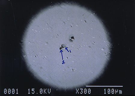
For this discussion, we are using the following definition for metal container cratering: “a defect in the interior coating film, where the coating is dewetted in a circular pattern, and a pit is present in the center of the crater.” In many of the defect cans inspected, there were two pits (double pit) in the center of the crater.
In the two-piece can industry, the presence or absence of craters is detected via a quality control, the metal exposure “quick test” after the inside spray coating has been applied and cured.
Early in the investigation, we observed that there was consistency in the location of the craters; that is, they were all on the interior side walls between one and two inches from the bottom dome of the can. Also, we did not see any craters in the bottom dome area of the can, or where there was a lack of metal deformation. There was also an absence of craters on the upper two-thirds of the side walls.
Background
This case study occurred at a Ball Packaging International North American multi-line aluminum can plant which supplies, mainly, beverage customers. Each production line had: (1) its own press to produce cups from aluminum coil stock, (2) bodymaker machinery to produce the drawn and ironed cans from the cups, and (3) a can washer system to remove residual oils and clean the aluminum for subsequent ink and coating application. In this plant, a new Quaker Chemical bodymaker lubricant/coolant was installed earlier in the year, supplying seven machines which were running for approximately nine months when the problem occurred. Up until this point, there were no previous unexplainable occurrences with high metal exposure readings.
During the cratering problem, the plant was able to identify that the source of the problem was the bodymaker lubricant/coolant system. They were able to take cans which were made from the Line 1 coolant system and divert those cans into the Line 2 washer, decorator (ink label application), and through the inside spray coating and curing ovens. The defect followed the cans from the Line 1 bodymakers through Line 2 interior coating ovens. The next experiment was to take cups that were feeding Line 1 and to divert them into the Line 2 bodymakers. The defect did not follow the cups into the system.
Another experiment, run by the plant to help eliminate the washer system as a potential cause, was to take some of the cans from Line 1 bodymakers, wash the cans only with an organic solvent, IC spray and cure the coating, and again test for metal exposure. The defect also occurred on the solvent washed cans.
In chronological order, we present a brief history of the cratering defect occurrences:
- Day 1 – Sporadic high metal exposure readings, primarily in the afternoon.
- Day 2 – Low readings in the morning. Higher readings in the afternoon, which continued into the night. Numerous changes were made in an attempt to eliminate this defect.
- Day 3 – Persistently high readings throughout the day; this was when the plant determined conclusively that the lubricant/coolant system was the source of the problem. The decision was made to dump the lubricant/coolant system, clean the tanks, pumps and piping, and recharge with fresh material.
- Day 4 – Lubricant/coolant system was cleaned out with a caustic cleaner and recharged with fresh material. One maintenance item that was found and repaired was a leaking heat exchanger gasket on the cooling tower water system. The bodymaker lubricant/coolant was circulated through this heat exchanger.
- Day 5 – The plant restarted on the fresh lubricant/coolant and the cratering problem was eliminated. All the metal exposure readings returned to normal very low levels.
Our initial theories were that some form of contamination was responsible for the cratering defect, either in the lubricant/coolant system or in the concentrated product bulk storage tank. In meetings with plant officials after the problem was solved, we formulated a three-pronged approach to identify the key assignable causes.
-
- The first phase of the investigation was to take a careful look at the defect cans to analyze what chemical or
physical changes had occurred on the surfaces.
- The first phase of the investigation was to take a careful look at the defect cans to analyze what chemical or
-
- The second phase was to take a detailed look at the lubricant/coolant samples obtained during the height of the problem to see whether we could detect any unusual changes which may have occurred.
- The third phase in our investigation was done by the plant where they were going to study and analyze
all their chemical processes to see whether any changes had taken place.
Analysis Conducted at McCrone Associates, Inc. Laboratory
Several of the aluminum cans which exhibited craters in the interior sidewall coatings were submitted to McCrone Associates, Inc. laboratory. The task was to conduct microanalysis of the craters to determine what contaminants (if any) were causing the cratering. The craters were examined by a variety of microanalysis techniques, including polarized light microscopy (PLM), scanning electron microscopy (SEM), energy-dispersive x-ray spectrometry (EDS), infrared microspectroscopy, and secondary ion mass spectrometry (SIMS).
Normally craters are initiated by a contaminant that is on the surface of the metal, which causes the organic coating to “pull away” from the material, resulting in the formation of a crater with the contaminant as a mound in the center. During the polarized light microscopy examination, it was discovered that deep pits were at the center of the craters rather than a mound of a contaminant.
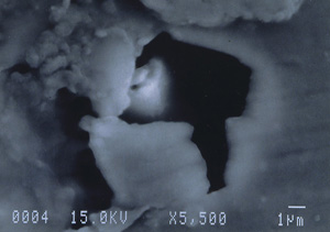
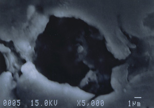
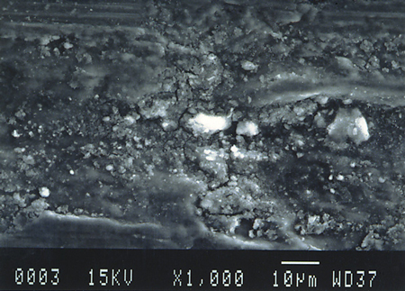
Further examination was conducted by scanning electron microscopy. Figure 1 is a low magnification scanning electron micrograph of a crater that is typical of those found in most of the cans. In each case, the pits appeared to be a double pit separated by a “bridge” of the metal. Figures 2 and 3 show higher magnification SEM micrographs of two of the pits. Several observations are worth noting: first, the perimeter edges of the pits are quite rounded as are the bottom features of the pits. This indicates that the pits are caused by a very severe and rapid corrosion attack, as opposed to fracture surfaces from pinholes or spalling. Another observation from the SEM examination was an absence of major amounts of visible corrosion products inside the pits. Normally, when aluminum corrodes in the presence of water, large quantities of aluminum oxides/hydroxides are formed, typically resulting in mud-cracking patterns.
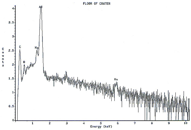
Analysis continued by using the energy dispersive x-ray spectrometry (EDS) system on the SEM to analyze the elemental composition of the pit walls and floors. The purpose of the analysis was to identify corrosion products, which usually provide clues as to the nature of the corrosive agents. Figure 4 shows an EDS spectrum of one of the pits which reveals the presence of carbon, oxygen, magnesium, aluminum, and traces of calcium and manganese. The magnesium and manganese are most likely from the alloying elements of the aluminum, although they could also be partially composed of carbonates from water. The calcium, and at least some of the carbon and oxygen, are probably from calcium carbonate. The remainder of the carbon and oxygen could be from small pieces of the internal organic coating. Other pits also exhibited a trace amount of sulfur, which would not be unusual, since the can washing process involved sulfuric acid solutions. Of major interest was the fact that oxygen was not excessively high, indicating a lack of aluminum oxides within the pit. The investigation continued by conducting x-ray analysis of the floor in the craters surrounding the pits, but no significant corrosion products were found, as shown in Figure 5.

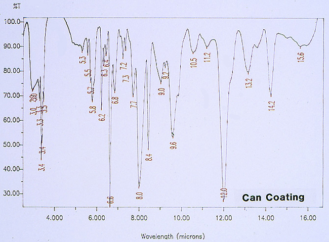
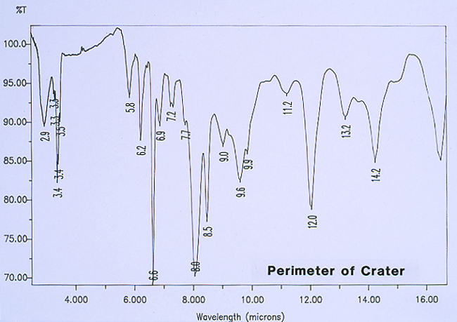
Since there was no evidence in the EDS analysis of major or even minor amounts of inorganic residues associated with the pits, the investigation continued by analyzing for extraneous organic materials. McCrone Associates, Inc. utilized an infrared microspectroscopy technique, using the specular reflectance mode, in order to obtain infrared spectra of various regions around the pits and the floor of the craters. The first step was to obtain the infrared spectrum of the internal coating, away from the crater site, which would later be used for comparison purposes to infrared spectra from the crater regions. Figure 6 shows the spectrum of the internal coating, revealing that it is an epoxy phenolic material. Figure 7 shows an infrared spectrum that was typically obtained from regions of the organic coating at the perimeter of the crater. Upon examination of the two spectra, it can be seen that there is certainly no evidence of major organic contamination at the crater site. A computer software program was used to perform a spectral subtraction of the internal coating spectrum from the spectrum of the coating at the perimeter of the crater. This technique is used to enhance subtle differences between infrared spectra. However, in this case, no difference was found between the two spectra, indicating that there were no detectable minor levels of organic contamination.
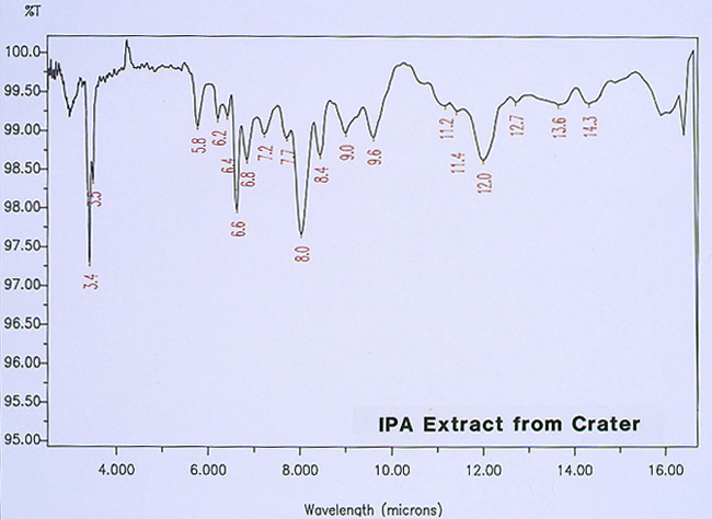
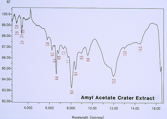
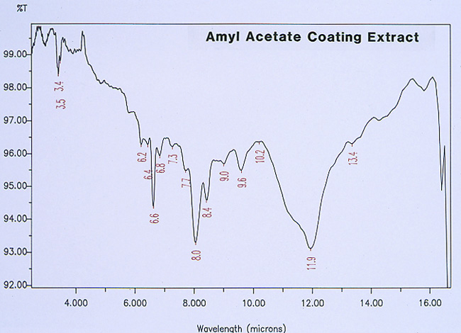
McCrone Associates, Inc. also performed micro extractions from the crater sites using isopropyl alcohol and amyl acetate to extract any non-polymerized materials from the crater sites. Similar extracts were conducted on the coating surfaces away from the craters for comparison purposes. The infrared spectra are shown in Figures 8 through 11. The only materials extracted from the craters appeared to be components of the organic coating rather than external contamination.

The apparent absence of significant amounts of corrosion products within the pits indicated that the corrosion reaction most likely occurred prior to the can washing operation. Any corrosion products that were present were most likely dissolved and removed from the pits during the can washing process.
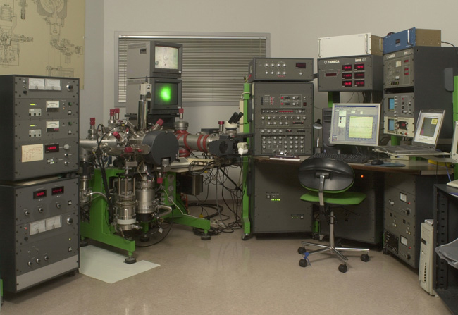
McCrone Associates, Inc. was requested to continue the analysis to identify potential corrosion products by using a more sensitive technique known as secondary ion mass spectrometry (SIMS); the SIMS instrumentation is shown in Figure 12. The detection limit is approximately two orders of magnitude lower than energy dispersive x-ray spectrometry, i.e., SIMS analysis is capable of detecting elements in the parts-per-million and, in some cases, parts-per-billion range. Another advantage of the system is that it can also detect all elements of the periodic table. SIMS is a technique which utilizes a focused beam of plasma ions (in this case, oxygen), which used to bombard the surface of a sample. The bombardment literally ionizes the material on the surface, and the ion fragments are collected and injected into a mass spectrometer detection system.
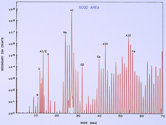
SIMS spectra were obtained from several pits and also surrounding regions of clean metal surface (after removal of the coatings in a
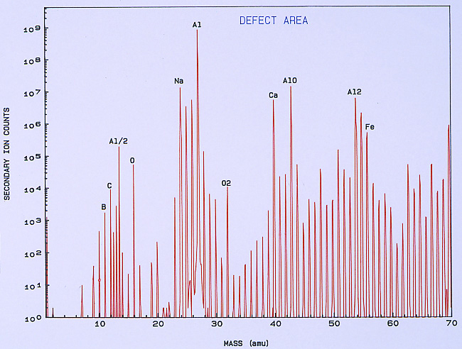
low temperature ashing system). Figure 13 shows a typical SIMS spectrum of the clean metal, which was used as a control spectrum for comparison to the pits. A few of the mass peaks have been identified showing the more common and major elemental components of the surface. Other peaks are various isotopes of the elements and also compound fragments such as oxides, carbonates, sulfates, and hydroxides. Figure 14 shows a SIMS spectrum that was obtained from one of the pits. When comparing this spectrum to that in Figure 13, it was noted that there was a significant increase in boron (relative to carbon) in the compared to the clean metal. It was also noted that there was a significant increase in calcium and iron within the pit, but this appears more subtle in the spectra because the Y-axis of each spectrum is in logarithmic units.
One of the techniques used in SIMS analysis is known as ion mapping, which is quite similar to the x-ray mapping that one obtains from a scanning electron microscope (commonly referred to as elemental or x-ray dot maps). In the case of SIMS, however, the maps are produced by ion fragments. The mass spectrometer is tuned to a specific atomic mass which can be either an element or a fragment, such as an oxide, a phosphate, a sulfate, etc. It was decided to map the various elements detected within the pit sites, while using a field-of-view that included the pit and the metal surrounding the pit. The most interesting maps were those for calcium, boron, and iron, as shown in Figures 15 and 16.
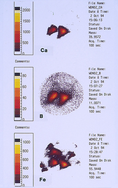

High concentrations of these three elements not only were found within the pits but it was also noted that they are associated with one another. The presence of calcium would not be uncommon mainly because it is a major component from water, but the presence of boron and iron seemed unusual and was certainly related to the pitting corrosion phenomenon. McCrone Associates, Inc. recommended continuing the investigation by looking for sources of iron and boron in the lubricant/coolant system.
Quaker Chemical Laboratory Results
Parallel studies were ongoing by McCrone Associates, Inc. on the surface analysis of the defect cans, and by the Quaker Chemical research laboratory on the analysis of the lubricant/coolant samples obtained during the cratering problem. Fortunately, this plant was on a schedule of sending a sample for routine analysis to the Quaker Chemical laboratory every Monday. This turned out to be most helpful since the problem started one day after the Monday sample was sent. During the midst of the problem, a five-gallon sample of the in-use lubricant/coolant had been captured.
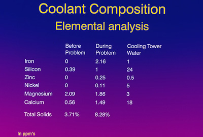
Extensive analysis of the lubricant/coolant samples was performed, and the most relevant data are shown in Figure 17.

Elemental composition of the “before” sample versus the during the problem” sample showed some significant differences: Note the absence of iron, nickel and zinc in the “before” sample and the presence of these elements “during the problem” frame. Something else very important to note is the ratio between the magnesium and the calcium for the “before” problem time frame. This ratio is about 1 part calcium to 3.7 parts magnesium. In the “problem” time frame, a significant change occurred to 1 part calcium to 1.2 parts magnesium. This was a dramatic change in the fluid chemistry, especially in a nine-month-old lubricant/coolant that had reached a quasi-equilibrium state.
With the surprising conclusion of a corrosive mechanism from McCrone Associates, Inc. plus the contamination findings from the Quaker Chemical laboratories, a meeting was held with the production plant management to share our information. This lasted for several hours and the plant personnel shared some information that they had discovered from their own internal investigation on changes that had occurred in their processes. Key comments from the plant personnel included:
-
- Initially, there seemed to be a pattern to the high ME (metal exposure)readings.
-
- From the review of the plant chemical process log, it was determined that excessive make-ups on the closed loop of the cooling tower water system had occurred.
-
- The bodymaker operators had noticed sporadic color changes in the lubricant/coolant, similar to the dye used in the cooling tower water system.
-
- The lubricant/coolant concentration was dropping during the “problem” time frame, indicating that some excess water was getting into the system.
- The heat exchanger was replaced as the lubricant/coolant was dumped and recharged. In this plant, the lubricant/coolant flow traveled from the central lubricant/coolant system, through the heat exchanger, directly to the bodymakers.
The main conclusion from this meeting was that substantial amounts of cooling tower water were clearly contaminating the bodymaker lubricant/coolant system during the “problem” time frame.
No one knew the impact of this, but the obvious next step was to take some samples of the cooling tower water back to the laboratory and analyze its components. Figure 18 is similar to Figure 17 with an additional column for the cooling tower water. Note the presence of iron, zinc and nickel in the cooling tower water; also note the magnesium to calcium ratio of 1 to 6. We also speculated that a borate corrosion inhibitor was used in the water, which would explain the presence of boron detected during the SIMS analysis. Our conclusion was that the cooling tower water contamination was the assignable cause of this ratio change during the crater problem.
Based on these findings, we hypothesized that the cooling tower water contamination might be the cause of the crater defect during the can making process. Additional samples of the cooling tower water submitted to the Quaker Chemical laboratory to see if this defect could be reproduced under laboratory conditions.
Simulation Studies
One of the lubrication test machines, the Falex Block on Ring device, was selected for these experiments. In this experiment, an aluminum alloy test block is seated on top of a rotating steel ring which is partially submerged in a test lubricant/coolant. A load is applied to the test block and the machine is run for a certain amount of minutes or revolutions. Typically, during this test, a wear scar will be generated on the block as the test progresses. The test lubricant/coolant is carried on the ring to the block-ring interface.
With this test device, several combinations of lubricant/coolant, with and without contamination of the cooling tower water, were run and their wear scars were analyzed by McCrone Associates, Inc.
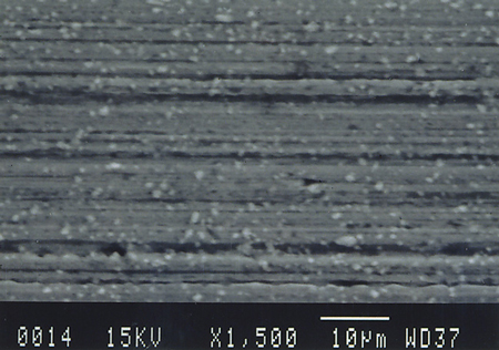
Figure 19 is the wear scar from the test using the lab-prepared sample of the lubricant/coolant used during the crater condition. Note the smooth nature of the wear scar. There is no evidence of any chemical attack or corrosion in this wear scar.
Figure 20 is the lubricant/coolant sample from the plant after the problem was solved, run under the same conditions. Again, notice the smoothness of the wear scar and the absence of corrosion.
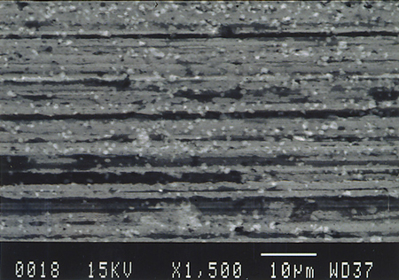
Figure 21 is the lubricant/coolant sample taken at the height of the cratering problem where there is substantial evidence that contamination by the cooling tower water occurred. Note the severe attack on the freshly machined areas of the wear scar.
Figure 22 is run under the same test conditions. This time, the sample is only the cooling tower water from the can plant. The corrosive attack from this material on freshly machined aluminum alloy surfaces is dramatic.

Summarizing these experiments, we find:
-
- Fresh lubricant/coolant showed no attack
-
- Lubricant/coolant with no cooling tower water contamination showed no attack
-
- Plant coolant contaminated with cooling tower water showed severe attack
- Cooling tower water alone showed extreme attack
Based on these laboratory simulation studies, we believe that the cooling tower contamination is clearly the assignable cause for the cratering defect experienced by this plant.
Conclusion
First of all, this project came to a quick and successful conclusion because there was a strong partnership between the vendor and the customer. This partnership is based on open communication, common goals, and mutual trust. Without this relationship, we might still be wondering today what happened.
Another element in the successful resolution of this problem was teamwork. The customer-vendor-outside laboratory team worked closely together with a strong sense of urgency, good project organization, and execution.
Finally, we believe that, during the can-making process, contamination of significant quantities of cooling tower water can react with the freshly ironed metal surface resulting in corrosion, gas formation and cratering of the inside can coating. It is recommended that can plants, using cooling tower water to reduce the temperature of their bodymaker lubricant/coolant, make sure that significant contamination does not occur.
Comments
add comment