Constructing a Scanning Light Photomacrography System
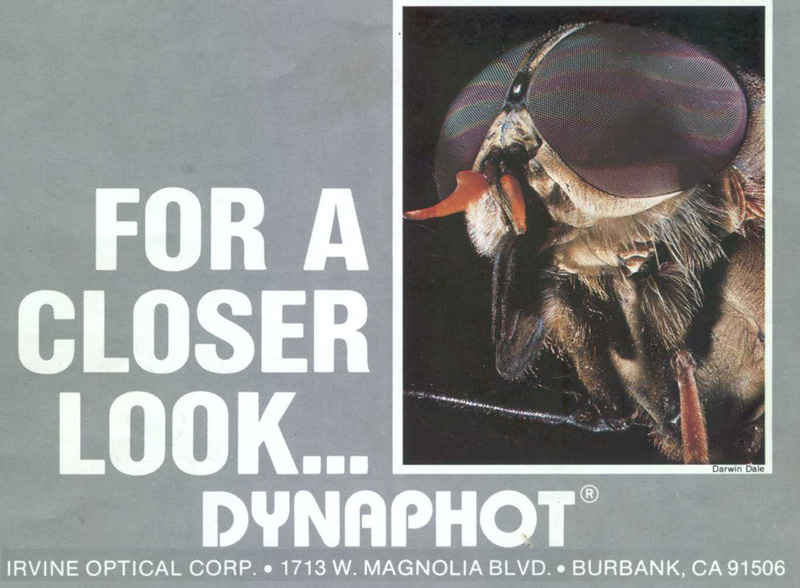
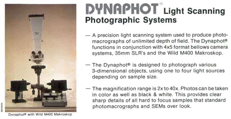
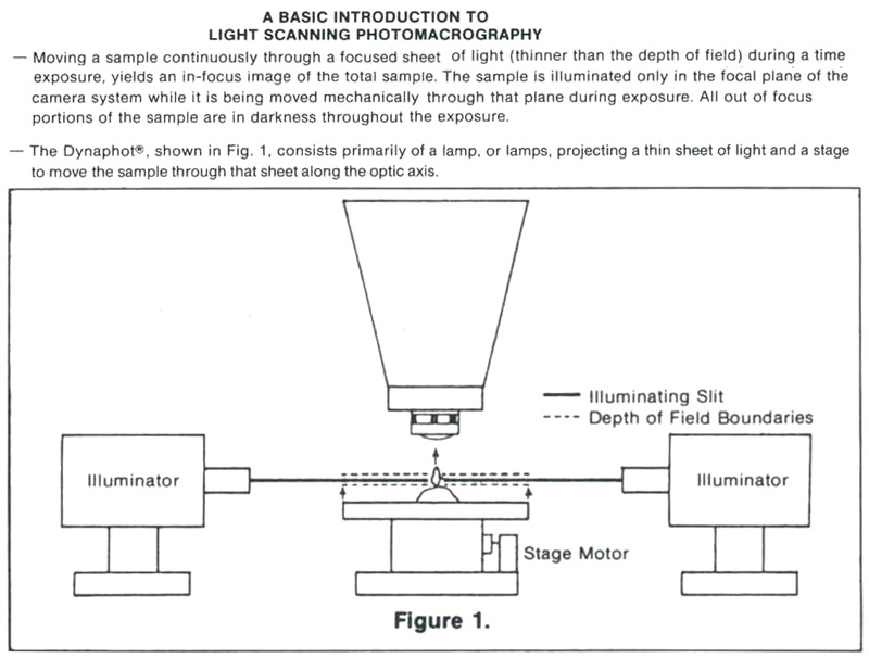
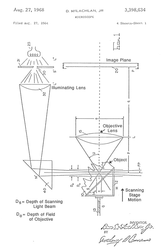
I was amazed by the scanning light photomacrography images Jim Gerakaris showed in his Inter/Micro-84 presentation a “Second Look at Scanning Light Photomacrography”. My own talk on “Method for Calculating Relative Apertures for Optimizing Diffraction- Limited Depth of Field in Photomacrography” complemented Jim’s talk by demonstrating the limitations of conventional photomacrography even with the aperture diaphragm stopped-down so much that the loss in image detail started to become visible.1 Jim’s talk was my first exposure to the apparently unlimited depth of field with the Dynaphot scanning light photomacrography system.2 My article on photography of fractured parts and fracture surfaces in Volume 12 of the ASM Handbook includes a description of the Dynaphot and comparison fractographs taken with and without scanning.3 This article also includes a table and graph based upon my optimum aperture analysis. The front cover of the Dynaphot sales brochure has a spectacular scanning light photomacrograph by Darwin Dale of the head of a fly, shown in Figure 1. The Dynaphot and its operating principles are well explained on the second page of the brochure, shown in Figures 2 & 3. There is some confusion caused by the brochure’s diagram in Figure 3, which claims that the specimen is scanned vertically through a thin sheet of light. The patent drawing by the inventor of the method, Dan McLachman Jr, clearly shows in Figure 4 that the beam of light from the slit lamps converges to a minimum thickness where it intersects the optical axis of the camera objective.
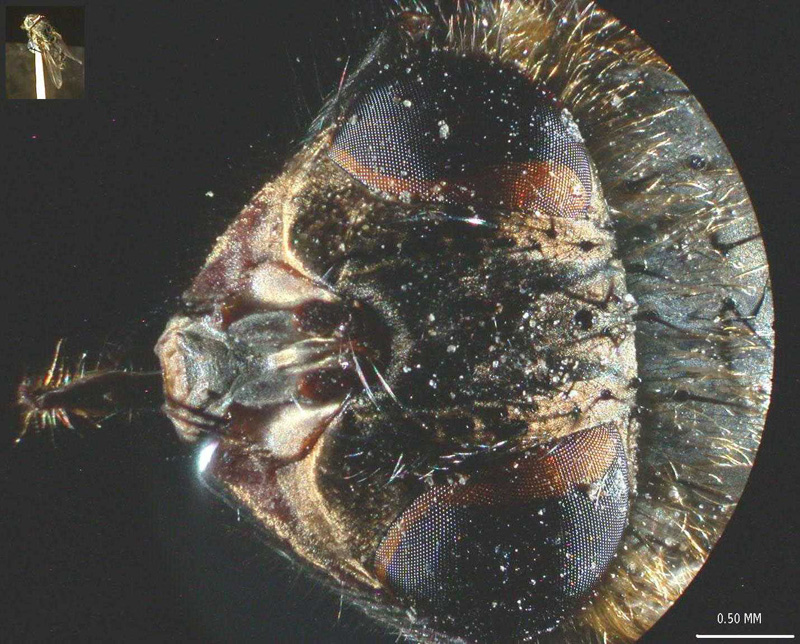
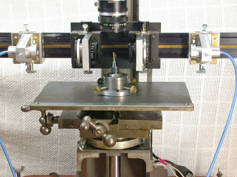
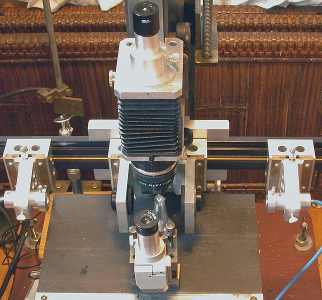
The effect of the illuminating beam converging and diverging at the edges of the field being recorded and the diffraction limited minimum beam thickness at the center of the field was the subject for my later publication of a mathematical analysis of the scanning method including a photograph and description of a scanning illumination system of my own design to be used on my very robust and precise photomacrography stand.4 This stand is intended for use in photographing parts and fracture surfaces of significant weight and is based upon restored components of an early twentieth century bench-lathe. The stand with the completed scanning light system is shown in Figure 5. A microscope eyepiece adapter with a 10X high eyepoint eyepiece is shown mounted in place of a parfocal Olympus 35 mm camera back. This eyepiece adapter was initially intended as an aid in viewing the fine details and as a relay lens for an eyepiece-mounted Nikon Coolpix 995 digital camera to be used for test exposures prior to final recording on film. I was pleasantly surprised to find that the test exposures with the digital camera were of high quality, even with the shutter held open on B (bulb) setting for 12 second scans. Figure 6 is a scanning light photomacrograph of the head of a house fly taken with this now completed system. The 35 mm film camera would record a much larger field area at somewhat higher resolution than the digital camera.
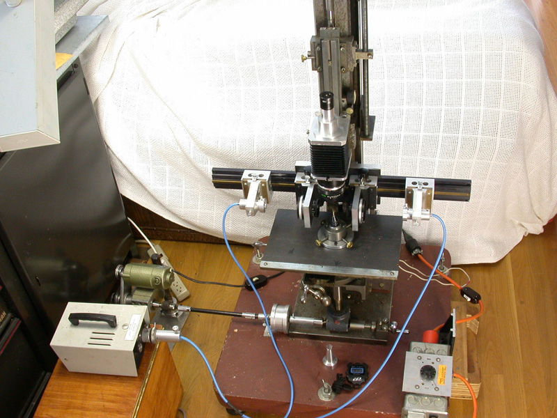
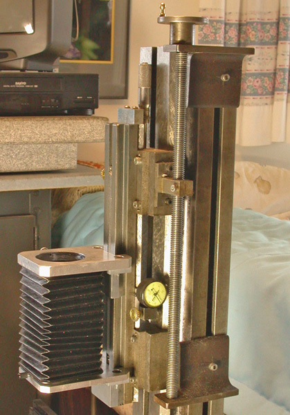
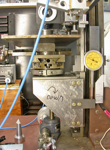
My photomacrography stand initially used the Olympus Auto Bellows, except for the bellows rail. The gray cast iron, double dovetail sided bellows rail for my stand is somewhat longer than the Olympus aluminum rail and held at both ends in sliders. These sliders mate with the guiding surfaces of the lathe bed vertical column for coarse adjustment of the bellows rail position using the long feed screw shown in Figure 7. These sliders are locked to the lathe bed before the adjustment for final focus is made with the micrometer head at the end of the bellows rail. The bellows rail dovetail and mating surfaces of the sliders were hand scraped for a very precise fit and alignment with the lathe bed axis. The all-metal camera and lens mounting boards shown in Figure 7, replaced the earlier Olympus components to provide much higher rigidity, and to eliminate the crack prone plastic inserts mating with the bellows rail in the Olympus system. The X-Y feed slides from the lathe are shown attached to a jackscrew driven knee slide in Figure 8. This slide provides the vertical feed for scanning when motor driven. The cast iron slide for the knee, made in my home shop, was precision hand scraped and fitted with a tapered gib for maximum rigidity. The dial indicator shown in Figure 8 is used to determine when to open and close the camera shutter. In order to assure the slide is moving at a uniform speed upward, I allow an initial 0.100” of scan travel before reaching the position where the shutter is opened with a cable release. An adjustable micro switch shuts off the scanning drive motor if it is not first switched off based upon the dial indicator reading for the end of the scan. The jackscrew, 0.025” elevation per screw revolution, is driven through a 20:1 gear reduction box salvaged from an electric drill. A 0.1 HP AC-DC motor with a belt reduction is used to drive the gear box through a flexible shaft. The motor speed is governed by a variable speed controller. The scanning exposure is controlled by suitable combinations of scanning speed and slit illumination intensity.
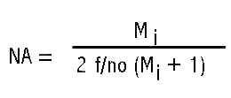
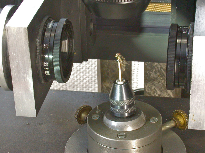
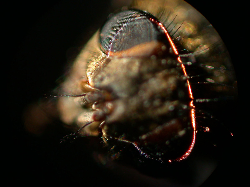
The illumination system described in my earlier article is shown in Figure 9 configured to scan the head of a fly, shown in Figure 6. Figure 10 is a close-up showing the fly between the illuminating lenses. The blue cables at the sides of the Figure 9 are portions of a bifurcated fiber-optic light-guide connected to adjustable sliders containing the slits. The ends of the light-guides are linear fiber arrays measuring 0.50 mm x 14 mm. These light-guide ends are positioned 6 mm behind the 10 mm long by 0.025 mm slit openings formed between two razor blade segments. The inner two sliders contain Spiratone macro lenses with a 35 mm focal length. Color balancing 80A filters are mounted in caps on the outer ends of these lenses. The system is configured to produce a 5 mm wide beam at 0.5X magnification of the slit sources to illuminate the fly head for the image in Figure 6 obtained with the Olympus 38 mm focal length macro lens set at f/4 with the bellows length set for 5X magnification. The illuminating lenses are set at f/4 giving an illumination NA of 80% of the imaging numerical aperture (NA). The numerical apertures are calculated from the following equation using magnification Mi = 2X for the cone of light illuminating the specimen. The lens relative aperture setting (f/no) is the focal length of the lens divided by twice the lens opening diameter.
Eyepiece inspection of the portions of the field illuminated by the slit system revealed objectionable diffraction artifacts when the illumination NA was reduced much below that of the imaging NA. This same condition applies to brightfield illumination with the light microscope.
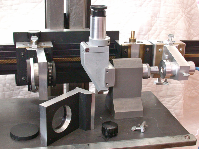
The sliders containing the slit sources and the lenses mount on a 610 mm long dovetail slide obtained from Edmund Industrial Optics. These sliders incorporate vertical dovetail mounts permitting the lenses and slits to be adjusted vertically for beam alignment. The aligning operation begins by rotating the caps containing the slits on the mating tubes containing the fiber-optic linear arrays until an image of the slit formed by the adjacent macro lens exhibits a full length image of the slit with uniform brightness. These angular positions are then locked with the thumb screws in the caps. The next operation is to align the slits so they are the same distance above the stage and parallel to the stage. A right angle monocular microscope with a 5X objective and 15X graticule eyepiece was fabricated for this operation shown being done in Figure 11. The next operation is to align the illumination lenses so that both beams are coaxial. The slit sources are moved to near the opposite ends of the horizontal slide for this operation with one of the illumination lenses removed from its mount. The remaining lens is then used to form the image of the adjacent slit on the end of the cap containing the other slit. The illuminating lens is then adjusted up or down until the image of the illuminated slit is centered relative to the opposite slit. The other illuminating lens is then installed for the final part of the aligning operation shown in Figure 12. The bellows lens with the 10X viewing eyepiece is used to center and focus the slit images at one of the sharp edges of an aluminum pyramid test target.The right angle microscope is also used for this operation as an aid for establishing precise focus of both slits on the pyramid edge. The illumination lens not previously aligned vertically is then adjusted vertically so that both slit images are exactly coincident on the edge of the pyramid when viewed with the right angle microscope.
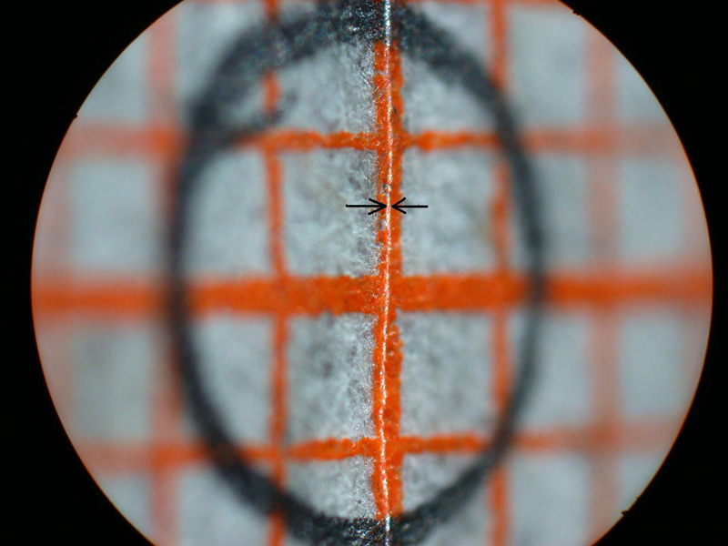
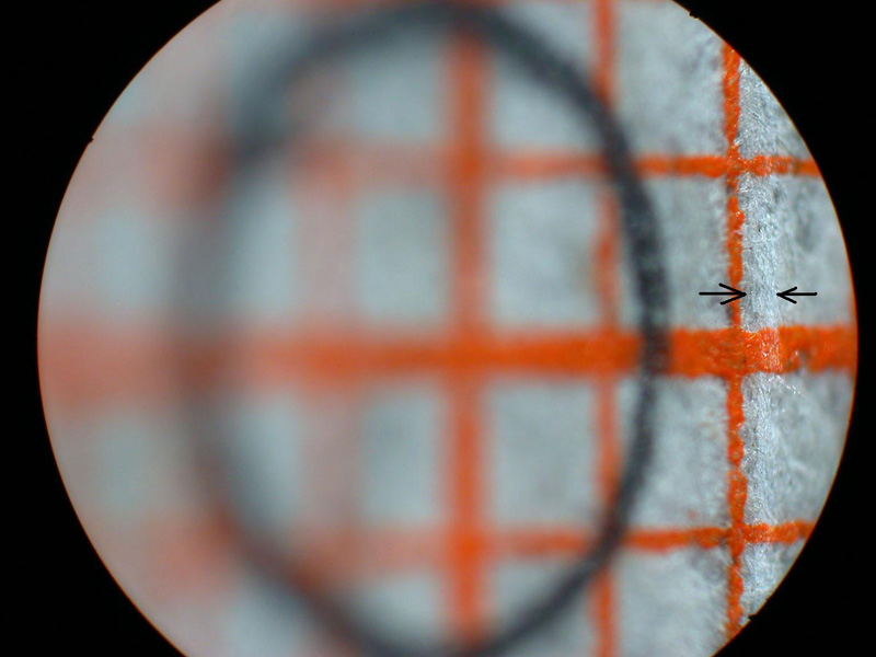
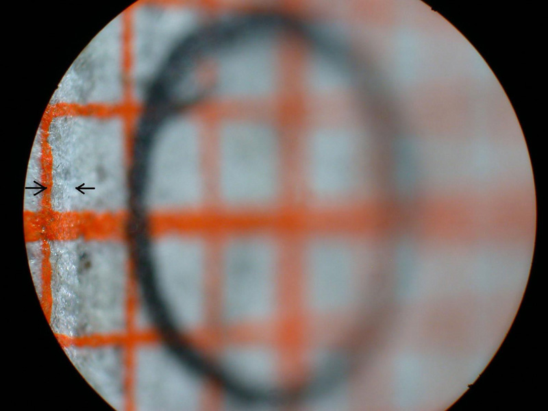
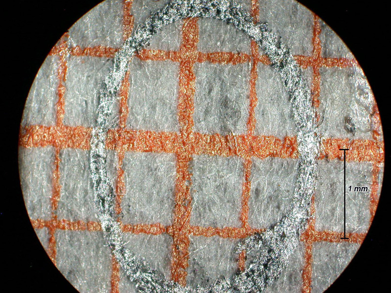
I expected the high magnification images to be the most difficult for this system to achieve with uniform high resolution and even illumination. My initial tests of the scanning system were with a 45 degree inclined flat target covered with a patch of mm graph paper and 5X magnification for the bellows lens set at f/4 for an intended 50X final magnification with an NA of 0.1. This target would reveal uneven illumination as well as variation in the resolution of the matted paper fibers. The graph paper was oriented so that one set of lines was parallel to the stage and facing one of the slit sources. A circle was drawn at the center of the target with a graphite pencil and the system aligned with the slit and camera lens both focused on the horizontal graph line passing through the circle. Figure 13 shows the very narrow scan line for this condition. The stage was manually raised and lowered for Figures 14 and 15. The scan line, indicated between arrows, greatly broadens near the edges of the field along the axis of the slit illumination lens so that it falls just within the high resolution portion of the depth of field. The system was covered with a light-proof cloth tent for the scanning light image of this target shown in Figure 16. Note that the illumination and paper fiber resolution are uniform across the entire field. The graphite coated circle becomes an ellipse with the graphite coating giving rise to specular reflection of the scanning light beam. This test needs to be repeated with recording on 35 mm film. The edges of the field in the direction of the short axis of the ellipse (highest and lowest portions of the field) would be expected to be blurred by the further broadening of the illuminating beam thickness with the field width 1.5 times wider on the film image.
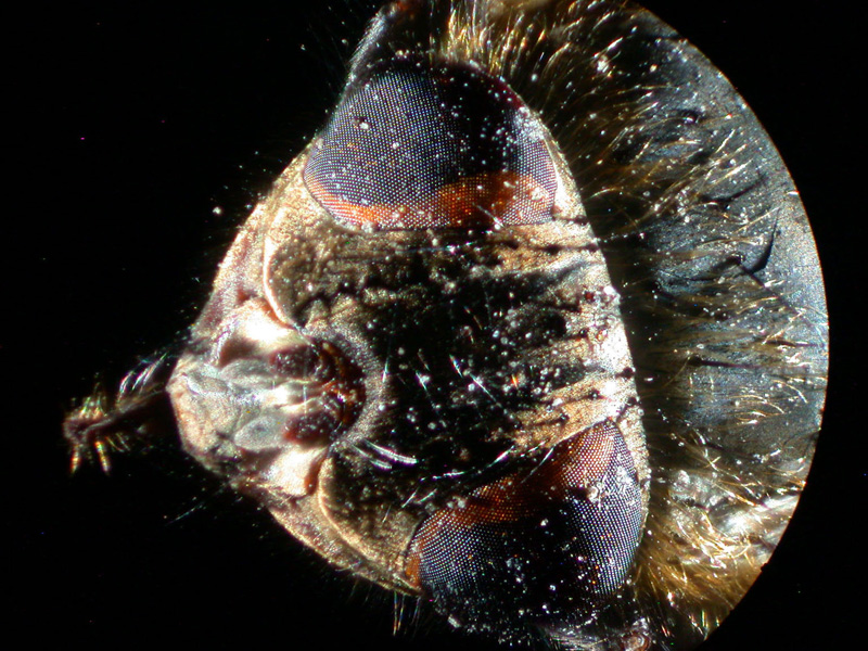
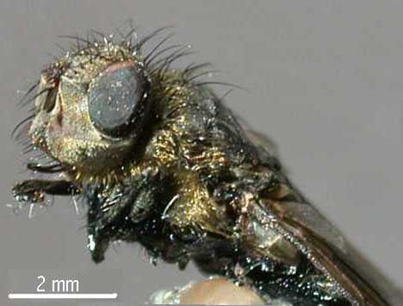
The fly head was photographed with the digital camera using broad area lighting from the side in addition to the stationary ring of light from the two opposed slit light sources for the image in Figure 17. This was done for comparison with a scanning light image of the same field of view shown in Figure 18. Comparison of these images demonstrates that the scanning method does not faithfully record the black hair patterns. Another problem with the scanning image is the lack of clues to judge depth of the features because the images are isometric projections and lack out-of-focus regions. This missing information is evident in the low magnification side view of the fly head shown in Figure 19. This conventional photomacrograph was recorded with the Nikon Coolpix lens at maximum magnification and broad area lighting. Engineering drawings typically contain front, top, and end views of a subject to aid in three dimensional visualization. Jim Gerakaris showed that the best way of obtaining the missing depth perception is to record stereo pairs with the scanning light method.
This article is the first progress report for my now functional scanning light photomacrography system. A large capacity eucentric stage has been built so that stereo pairs can be easily recorded. This stage was described in my article Eucentric Stage for Recording Stereo Pair Photomicrographs, originally publshed in the September 2005 issue of Microscopy Today. My original calculations of the field size limitations of the scanning light method need to be revised now that I know that the NA of the illumination beam must be significantly greater than anticipated. The theoretical field size limits need to be verified by experiments using 35 mm film recording covering a wide range in magnification. These results can be the subjects for future articles.
References
- Clarke, T. M. “Method for Calculating Relative Apertures for Diffraction-Limited Depth of Field in Photomacrography”; The Microscope 1984, 32, 219-258.
- Gerakaris, J. “A Second Look at Scanning Light Photomacrography”; The Microscope 1986, 34, 1-8.
- Clarke, T. M. “Photography of Fractured Parts and Fracture
Surfaces,” Metals Handbook, Ninth Edition, Volume 12, Fractography, ASM International, 1987. - Clarke, T. M. “Image field Size Limitation for Scanning Light Photomacrography”; The Microscope 1993, 41, 21-30.
Comments
add comment