A Rudimentary Treatise on Microscope Work, and the Construction of a Davis Diaphragm
Harold M. Malies (1920-2010); posthumous publication.
[Editor’s personal note: Many readers will recognize the name of Harold M. Malies as the author of the books Applied Microscopy and Photomicrography and A Short History of The English Microscope, or as editor of the journal The Microscope, succeeding founder Arthur L.E. Barron. He also wrote about twenty articles for this journal between 1940 and 2007. Harold was a mechanical engineer who, as managing director of Malies Instruments, performed contract work for much of the U.K.’s optical industry, and produced the first dispersion staining objectives sold by McCrone Associates.
I bought my first copies of Baker’s Microscope from Harold in 1968, and much of his pond dipping equipment. In the 1990’s I proposed making both a Davis diaphragm and a Traviss expanding stop in my own home machine shop, as these useful accessories were commercially made in very small numbers, and had become quite scarce. I wrote to Harold to learn if he had any working drawings for either of these. He did not, but this gave me an idea: I asked him if he would consider writing a regular column called something like The Home Shop Machinist, in which he would discuss the machining of microscope accessories. He thought this was a good idea, and something he could and would like to do. Harold thought a good place to start would be a general discussion of materials and methods and, as a first construction project, a Davis diaphragm using a commercially available small iris diaphragm (Figure 1). He wrote and submitted the first article, but I am sorry to say that for regrettable reasons the idea for such a column was rejected—a grave pity. I recently came across this unpublished article, and thought it was a shame that it, and succeeding articles, never saw the light of day; consequently, I decided to edit it and make it available here as Harold’s final, posthumously-published article.
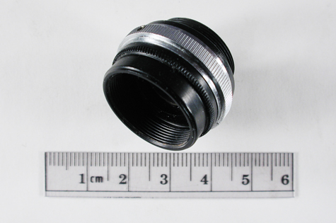
For those who do not know, the Davis Diaphragm (Davis Nosepiece Shutter; Davis Shutter; Dancer diaphragm) is, basically, an iris diaphragm fitted in an adapter to interpose between an objective and nosepiece, the adapter having male RMS threads on the top and female RMS threads on the bottom (Figures 2 and 3). It is used to increase depth of field and is also used for darkfield work; it is best used with low magnification objectives (Figure 4). The Traviss expanding stop is a substage condenser accessory for darkfield work. Commonly, a series of “spots” or “stops” are used to block out all axial, central rays of light, and allow only oblique, peripheral light to pass through the specimen plane—the normal aperture diaphragm being left wide open. A series of such stops are required, as their diameter depends on the numerical aperture of the objective in use. In 1906, W.R. Traviss described the construction of an ingenious expanding stop whose principle of mechanism is the converse of that of an iris diaphragm; thin metal sheaves are so pivoted that instead of producing by their movement a circular opening of adjustable diameter, they produce an expanding disc; in use, the operating handle is merely adjusted for optimum darkfield with objectives of any numerical aperture [Note on an expanding stop for dark-ground illumination. Journal of the Quekett Microscopical Club 77-82 (1907)]. How I wish that Harold’s column of articles had come to pass, because I see in one of my letters from him that he proposed the brilliant idea of combining the Davis diaphragm and the Traviss expanding stop in a single substage assembly so that rings of any diameter and width could be used as phase annuli to work in conjunction with the phase rings in any phase contrast objective! –John Gustav Delly]

W. Watson & Sons, Ltd. Catalogue of Microscopes and Accessories, 36th Edition.
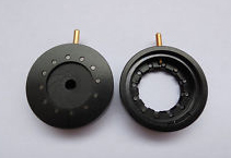
Swift (England) Davis Diaphragm ~1950s – 60s.
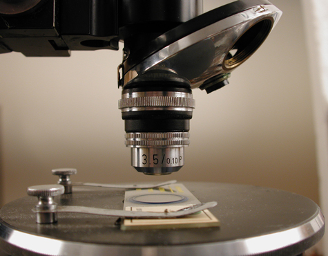
Davis Diaphragm installed, using low magnification objective.
Part I: General Considerations
A feature of Victorian publishing was the production of “Rudimentary Treatises” covering a range of useful subjects, and including the kind of information needed at the outset of a practical approach to them. I have such a volume on the steam locomotive which specifies the sizes and distances apart of rivets, and the reader finishes this modest book surprised that he now possesses much of the information needed to build the small simple engines of the early 19th century. The following notes on instrument work are offered with attention to the grammar of the subject, so that the reader need not be concerned as to how far along the road he might ultimately like to go.
There are three materials with which the microscope worker is chiefly concerned: these are brass, aluminium alloys, and steel. A type of steel of particular interest to the reader is what is broadly known as carbon steel, and the term here refers to iron with a carbon content ranging from about 1.0 to 1.5 percent. Carbon steel, by means readily available, can vary in hardness over a wide range so that, for example, a tool can be made which will cut a second piece of the same steel. Many cutting, grooving, or shaping operations are most easily and neatly performed by making an appropriate cutter from the steel in the soft state and then hardening it; these procedures will be described later.
Carbon steel is readily available as round stock from about 1/32 inch diameter to a couple of inches or more; it is known as drill rod in the U.S., and in England as silver steel (it contains no silver). Flat steel plate having similar properties, and accurately ground to stated thicknesses, is sold as “gauge plate.” Mild steel, which contains a much smaller proportion of carbon than carbon steel, is often used as an economical alternative for brass or aluminium. The machining properties of some grades are very poor and for our purposes “free cutting” quality should be specified. The hardness of mild steels cannot be manipulated in the manner of carbon steel, and it is never used for making tools; it can be hardened on the surface.
Brass is an alloy of copper and zinc in which the proportion of zinc varies from about 20 to 40 percent. What are known as “turning brasses” have their machining qualities improved by the addition of lead and by heat treatment during manufacture. When turned, the swarf (fine chips of metal produced by a machining operation) breaks into tiny chips, and good surface finishes and close dimensional limits can be obtained. However, they will deform or bend well, and as knurling is a forming process the “teeth” of a knurl tend to break off. A brass known as Y metal or knurling brass is, by contrast, ductile, but when turned makes long troublesome fronds of swarf which must be constantly cleared.
In microscope work, aluminium alloys have largely replaced brass, because they are cheaper and lighter, and can be finished very conveniently by anodising. The alloys closely reflect the properties of brass, and free turning grades should be ordered. Other alloys encountered occasionally include German silver, or white brass, a zinc copper nickel alloy that machines well and is sometimes chosen for its silvery white appearance. Gun metal is often used for small castings, it is an alloy of copper and tin which many foundries prefer to brass and which machines well. Cast iron is useful for castings of appropriate size; it is iron typically containing around four percent of carbon; it machines well with the slight disadvantages of being dirty to work with.
It is assumed that the reader has access to a simple screw-cutting lathe. If he is at the point of obtaining one, it ought not to be too small; that is, it should take a chuck not less than four inches in diameter, and it will be useful for the lathe to have a set of collets. The use of a small milling machine will be helpful. In its absence, there are milling attachments for the cross slide of the lathe that can be used for light cuts, slots, etc. The combination tools intended to unite the function of a lathe and a mill, those of them that we have seen, are seldom very satisfactory, as either being too small even for microscope components, and lacking rigidity; their use is a rather esoteric taste.
In choosing material for a project, consider the finishes available. The surfaces to receive a protective or ornamental finish must be as the lathe leaves them in the case of turned parts, there being no justification for using emery cloth nor any need for it if the tool is correctly shaped and sharp, and on the axis of rotation. For finishing flat surfaces in small components made from brass or aluminium alloys, excellent results can be obtained by rubbing with Water or Ayr stone (Tam o’ Shanter hone). This is a very soft grey stone which should be used with plenty of water; parts finished with it will not exhibit the rounded edges that emery cloth produces. The stone is now expensive because the factory in Scotland burned down; it could be had in a range of sizes; it is softer than Arkansas stone which should be preferred where it is required to remove more material.
Brass surfaces do not deteriorate, they are finished for ornament. As it is the fashion that they should be white they are commonly given an electro-deposited coat of nickel, followed by a light deposit of chromium. If a polished finish is required the work is polished before plating; for a pearl finish the polishing is omitted, and the very fine grain of well-executed turning disappears during the plating process.
Since chromium plating puts some 1-½ ‘thous (0.0015 inches) on the surface, it is not usual to plate where dimensions are closely controlled. In the case of threads, there may be extra build-up on the crests of threads where the current density is disproportionately high, and this must be allowed for when cutting the threads. Gear teeth, incidentally, should not be plated. As a finish for brass, the old hot lacquering method is worth considering, because the workman can do it as the parts are finished. Many components need to be blacked, and a bronzing solution for brass (it affects nothing else) can be made as follows:
- Basic copper carbonate CuCO₃Cu(OH)₂H₂O 50 gm
- Ammonia, 0.880 specific gravity 400 ml
- Distilled water 800 ml
Add about half the carbonate, a little at a time, to the ammonia, agitating the stoppered bottle between each addition; add the distilled water and continue.
The brass component, on a copper wire, is dipped in hot water, shaken, and immersed in the blackening solution with movement. After half a minute it is rinsed in hot water and dried, when it should be darker or even sufficiently dark; usually it will need to be returned to the solution for a further half minute before hot rinsing and drying. The fresh solution produces a beautiful dark purple-blue which, if immersion is continued, is quickly succeeded by black-brown. The solution can be used a number of times, becoming slower and giving black-brown rather than blue colors. As this is a pure stain it conveniently puts no thickness on the work; the color will stand vigorous drying on a cloth but not constant handling, for which it needs to be lacquered. On internal surfaces it can be left.
The lacquer mentioned above is the original instrument finish, and the lacquers are solutions of shellac in ethyl alcohol with coloring agents. Have the lacquer in a wide-mouthed container with a wire across it on which the brush can be wiped nearly dry. The brushes are flat and very soft, and for small microscope components should not be less than half an inch wide. The work is heated to about 80°C and successive thin coats are brushed on with slow strokes in the direction towards the body, re-warming the work and repeating until the desired color is obtained: three coats is usual. Round work can be lacquered in the lathe, run very slowly to avoid multiple coats. Tubes should be placed on a piece of wood and held in the hand. Any work in aluminium alloys should always be anodised as the reactive metal will otherwise undergo surface changes. The anodising process forms a layer of aluminium oxide which can be dyed whilst fresh and soft, the undyed film being colorless. Light cuts cannot be taken on an anodised surface, and any modifications must be done before anodising, and likewise engraving because an anodised film will break at the edges of the engraving cut and detract from the appearance of the lettering when filled with engravers’ wax. An allowance of about half a ‘thou (0.0005 inches) should be made for each anodised surface, i.e. one ‘thou on a diameter, and three times this on screw threads where the anodic film builds up on the crests due to the higher current density. Opposing anodised surfaces, being composed literally of sapphire, do not work well together unless lubricated with a heavy long molecule grease (fat). Excellent synthetic lubricants are available; a traditional fat, very good if the others are not available, is anhydrous lanoline (wool grease) melted with a little thick gear oil.
Components made from steel should be chromium plated. Stainless steel parts are, of course, left natural, but even the so-called free-cutting grades of stainless steel are slow to machine and cause more tool wear than ordinary free-cutting steels.
PART II: Constructing a Davis Diaphragm
As a worked example consider a Davis Diaphragm (Dancer Shutter; Davis Nosepiece Shutter; Dancer Diaphragm). This is an iris diaphragm interposed between the objective and the nosepiece, and used to control the cone from the objective back lens, usually of low power objectives. It has male and female Royal Microscopical Society (RMS) threads which need to be concentric with one another and with the iris itself.
The RMS thread has a nominal diameter of 0.8 inches and 36 threads per inch, 55° Whitworth form. It was defined in 1865 with gauges by Joseph Whitworth, and is the subject of standards in a number of countries. All the standards are interchangeable, and the thread is one of very few things uniform throughout the world. Earlier threads were all smaller than the 0.8 inch size which was a suitable choice for the very large back lenses of such objectives as the 12X apochromatic of 0.65 N.A. Note that male and female RMS threads made to standard do not fit especially closely, having a clearance that approaches two ‘thous at its minimum value, and this is important since, as the screw tightens, the flange of the objective mount squares to the opposing face on the nosepiece, and also draws to the center. The consistency of this centering action has been investigated in the past and was found to be adequate for the centration requirements of objectives of all powers. A pair of threads in brass should be turned up for use as gauges, to avoid the temptation to borrow objectives for trial fitting—a bad practice since objectives anyway exhibit variations in thread dimensions.
The iris diaphragm in a Davis diaphragm should open to about 16 millimeters, the one used in this exercise having an external diameter of 1.025 inches and width 0.275 inches. Brass or free-turning aluminium alloy can be used for the two turned parts; in the present instance, a piece of 1-⅛ inch diameter bar long enough to make both parts and to leave at least ¾ inch in the chuck. Begin by drilling the piece of bar right through with a 21/32 inch drill held in the tailstock of the lathe, and then turn the portion for the male RMS thread to a diameter 0.797 inches. The undercut should be turned at this stage and must be not less than 0.020 inch deep on radius. The thread itself can be cut with a 55° V-pointed tool but is done much better with a thread chasing tool, 36 threads per inch Whitworth form, this will give a thread of correct profile. Using a thread chaser, the depth of thread, from just touching the work, should be 0.018 inches, obtained with three cuts, the lathe running very slowly or even in back gear, and followed by a cut made without altering the final setting. Note that if the pitch of the lathe lead screw does not divide into 36 (most do not) the cross slide must not be disengaged from the lead screw between cuts; simply wind back the tool clear of the thread and reverse the motor to make ready for the next cut. If a V-point tool must be used, the thread depth will be about 0.023 inches leaving a flat topped thread. The piece of material can now be given a very light skim (or “witness”) on the 1-⅛ inch diameter as a finish, and parted off to length.
Next, the second component is made from the material still in the 3-jaw chuck. It already has a 21/32 inch hole through it, and it should now be bored out to 0.766 inches, a distance of half an inch or so sufficing for this bore on which an RMS thread is turned, again preferably with an internal thread chasing tool, and, if one is not available, with a corresponding V-tool, the respective thread depths being as for the male thread. Try the male component, which will be rather slack if allowance has been made for anodising. If the components are brass and are to be plated, it is best to have the plater mask and leave the threads un-plated. If using aluminium, masking anodising is not practical, and to allow for the thickness of the anodic film, the diameter of the male part, before thread cutting, should be reduced by 0.002 inches and the diameter of the female similarly increased.
The partly-made component in the lathe now serves as a screw chuck to finish out the first component, which is screwed into it with a little oil, and the turning completed in accordance with the drawing. Remove it, and on the part still in the lathe turn the 1.025 inch internal diameter which will thus be concentric with the RMS thread. The only turning that remains is the 0.910 inch diameter; this fits the air and has no requirement of concentricity. It can be formed by using the parting tool for successive plunge cuts followed by a very fine finishing cut with the same tool before parting off. Note that when the second component was used as a chuck to hold the first, a small cut was made at 45° on the internal edge because the angle of the part being screwed into it is seldom or never absolutely sharp, and if there is any radius there it must interfere with the ability of the faces to come into perfect contact.
Because RMS threads are required constantly it is worthwhile making up a pair of RMS screw chucks with ½ inch or 3/8 inch shanks which can then be held in a collet. The operation to form the 0.910 inch diameter just described could be conveniently performed on one of these.
The 0.85 inch cut out shown in the engineering drawing below is ideally made using an end mill in a milling machine. If this is not available it can be filed out with a thin metal disc dropped into the cup of the part, when filing down to the disc will ensure a clean bottom edge. Use a pillar file or “engineer’s file” which is parallel and has a smooth safe edge, used to guide the file in contact with that part of the component which it is not required to cut. It remains to drill two countersunk holes, and two tapped holes for the screws which hold the two components together.
The two parts of the assembly are dimensioned so as to trap the commercially available iris diaphragm and prevent it from turning within the housing when the two screws are tightened. If necessary, the trapping action can be relieved by taking a very fine skim, before anodising, on the surface S. It is unnecessary to allow for the thickness of the anodising on the surfaces securing the iris.
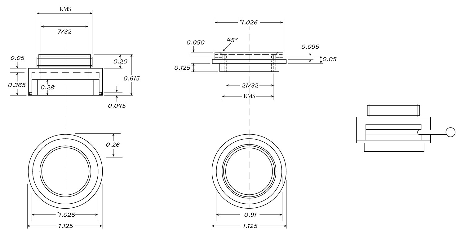
Print an 8-1/2″ x 11″ copy of this engineering drawing.
Comments
add comment