The Curse of the Light Microscope
October 18, 2017
Presenter: Wayne Niemeyer, Senior Research Scientist, McCrone Associates
As microscope users learn more about light microscopy through “brute force” experience, reading microscopy literature, participate in formal training classes, and attend microscopy conferences or symposiums, the curse becomes obvious: it is selecting the proper lighting to see what is really there! This webinar explores numerous microscope lighting accessories and how they reveal and/or enhance previously unseen features in a variety of samples. 43 minutes.
Transcript
Charles Zona (CZ): My name is Charles Zona and I would to welcome everyone to today’s McCrone Group webinar. Our presenter is Wayne Niemeyer of McCrone Associates. Wayne is a senior research scientist with McCrone Associates and has over 40 years of experience. Wayne is going to talk to us about The Curse of the Light Microscope. Most of you probably know Wayne as an expert in electron microscopy; however, Wayne is also an accomplished light microscopist as well, and uses a wide variety of light microscopy techniques, including polarized light, fluorescence, and many other contrast methods. For Wayne, the curse of the light microscope began well before college; in fact, it started when he was 10 years old after receiving his first light microscope as a gift. Wayne is going to tell us what the curse of the light microscope is all about and then field questions from the audience. This webinar is being recorded and will be available on the McCrone Group website under the webinars tab. Now I will hand the program over to Wayne.
Wayne Niemeyer (WN): Thank you, Chuck, and welcome everybody. I certainly appreciate all of you taking time out from your busy schedules to join us today. I am going to talk about the curse of the light microscope—at least I call it a curse. It is a good time to talk about curses, being the month of October with Halloween coming up later at the end of the month, and tomorrow is Friday the 13th, and we know what that means. Chuck mentioned that we have had this curse for a long, long time. As he said, I’ve had it since I was 10 years old, but the curse goes back way farther than that, actually. I can give you some historical development of the microscopes and where the curse actually began.
Circa 1590, Hans and Zacharias Janssen combined two simple microscopes to form a compound microscope. Then, circa 1665, Robert Hooke devised the compound microscope to observe opaque objects. You’ll recognize the name of Robert Hooke because our Hooke College of Applied Sciences is named after him, in his honor. Circa 1681, Christian Huygens invented an ocular for the telescope, which was later adopted universally for the compound microscopes. Around circa 1800, Thomas Young corrected lenses for astigmatism. Circa 1873, Ernst Abbe designed the chromatic substage condenser, which you find is furnished with many of today’s microscopes. In 1886 or so, Abbe, Schott, and Zeiss collaborated to perfect apochromatic objective lenses. Circa 1900, or around 120 some years ago, the compound microscope had essentially evolved into its present form.
As we all know, there’s been lots of activity going on, microscope improvements, modularization of microscopes in today’s world, and all kinds of accessories and filters and so on, that come with them.
If any of you get a chance to come to The McCrone Group here in Westmont, Illinois, I really urge you to take some time out to visit our microscope museum. It’s the Brooks Collection of Microscopes. Don Brooks is the owner, CEO, and chairman of The McCrone Group, and he has, over the years, acquired so many of these antique microscopes, and there are a lot of them are on display now, here. Approximately 200 are on display, and another 200 to 300 are in storage. The earliest microscope in the collection is circa 1680. The collection also includes about 2,500 volumes of books on microscopy and optics dating all the way back to 1630. It’s an incredible collection, and it’s an incredible site if you can get some time to tour. On the right-hand side here, we have a couple of microscopes from his collection. One is from 1870, and the other one from the mid-1700s. These are fully functional microscopes, still, after several hundred years. Notice on the circa 1870 microscope, those of you that have compound microscopes, you probably recognize the substage condenser that is right below the stage and above the little mirror. That condenser still looks very similar on today’s microscopes, over 200 years later.
So what happens with this curse? It begins and intensifies as soon as you buy or inherit any microscope. That’s why it started with me when I was 10 years old. It starts to intensify as you start using your microscope to examine various objects, and then and intensifies even more as you learn about microscopy through your brute force experiences, reading various microscopy literatures, participate in formal training classes like they have here at the Hooke College of Applied Sciences, or attend microscopy conferences, seminars, and webinars like you’re doing today.
So, what is this curse? Simple. Its lighting. Just lighting techniques to view objects under the microscope.
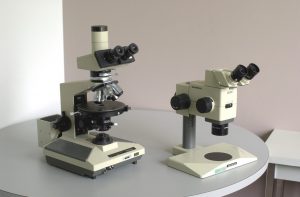
Here are examples of a basic compound and stereomicroscope, circa late 1980s when these first came out.
These are the two microscopes that I inherited here at McCrone Associates when I started here in 1992. These are just basic scopes, but as the curse starts to intensify, you want to add to it—and it’s lighting that you want to add.
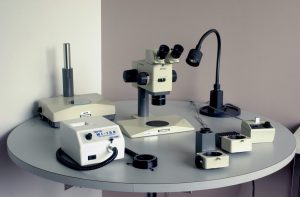
So, here’s what happened with the stereomicroscope. We included some extra lighting on the back left side is the stage which has transmitted light capability, which replaces the normal stage that’s in the center. Then, in the left-hand front, we have the ring light. This ring light attaches to the base of the objective lens to provide nice circular lighting around sample. We also have to have some sort of a module to attach a camera to it now. Then we have what’s known as coaxial illumination, where two parallel light beams come down to the surface of the sample and reflect back up through the objective lens. You also need oblique lighting, and for that I like to use the black gooseneck halogen lamp in the back here and that really floods the entire field of view with a nice bright light.
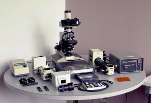
The compound microscope is more complex, and this is only a selection of some of the accessories that you get for the compound microscope that I have here. There are all kinds of filters, prisms to insert, different light sources to insert into the system, and you certainly can do about reflected light and transmitted light, that sort of thing, and you can use that gooseneck halogen light for some oblique lighting, as well.
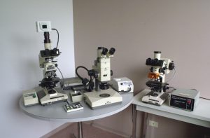
We are going to put all the stuff together on the circular table. That’s the final set up, as I call fully equipped. It’s not really fully equipped because there really are more accessories that you can get for it, but this is the fully equipped system that I was using. On the right hand side, we have another compound microscope specifically set up for fluorescence microscopy work. That was done because the fluorescence light source is different than the standard light source, and you have to keep switching them back and forth on the compound microscope with you just have one. This way we had a second one that we could just dedicate to the fluorescence work.
I am going to show you some examples of different lighting conditions taken from the stereomicroscope, but first I want to give you what I consider minimum requirements for illumination systems for your stereomicroscope.
First of all, you need some oblique lighting capability, then you need the reflected coaxial illumination, then a ring light, and finally transmitted brightfield and darkfield lighting. I will give you some examples of these various things.
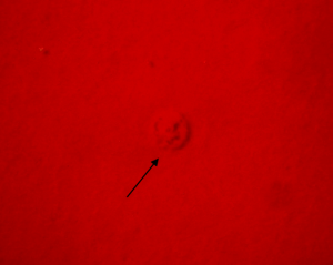
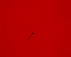
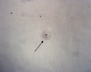
Here’s a crater defect in paint. A crater forms in paint when it’s applied and there is a contamination on the surface of the substrate where the paint is not compatible with that contamination, and it pulls back in a radial fashion from the contaminant and forms a nice circular ring with a ridge around the outer perimeter and a depression inside where the contaminant will reside. So, with oblique illumination, in this case, the oblique light is coming in from the right hand side of the image, and we can see that the right-hand side of the crater is dark on the inside of the wall of the ring and the shadow, and then on the other side. It’s not shadowed anymore, so the inside wall is brighter. Inside, we can see some sort of contrast/shadowing effect, but it is not a really good way to look at the crater defect in the paint.
If we use the ring light, we can see now that that crater is pretty much invisible. We can’t really tell much of anything about it, and that’s because the ring light is producing light source from a cone, if you will, all the way around the 360°, so it’s eliminating all the shadowing effects. On flat surfaces like this, or for surfaces that have very small topographical features, a ring light is not really going to help you very much.
The coaxial illumination, though, is really fantastic for the smooth type surfaces. Here is the paint crater. Now we can clearly see it in the center of the field of view, here, and right in the center of that circular region is our little black contamination material. Now we can get in there, as we are viewing it in the coaxial illumination, and we can isolate that contaminant particle and mount it for other analyses to find out what it is.
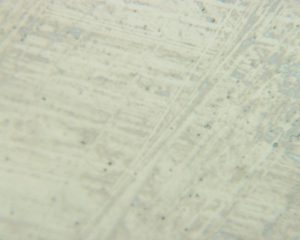
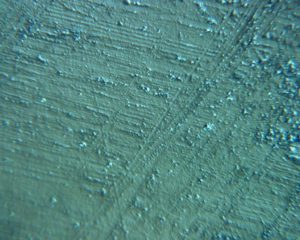
Here is an example of what I call comet defects on polished brass. With oblique illumination the polished brass doesn’t look all that bright, and you can see bright speckles and lines, and so forth, from the various ridges in the topography of the brass.
If we look at it with a ring light, now we can see a little more detail, and you can see the two bright spots to the upper right and lower left side of the image and kind of a wispy tail coming down toward the bottom of the image from each of those spots. Still not real good detail—not a really good view of it.
Let’s go back to the coaxial illumination again. Now we can really see the fine details on the surface. Look at the difference in the roughness of appearance compared to the oblique and ring light illumination. Coaxial illumination is just fantastic for what we would consider smooth samples, and dark materials, like the red paint and even black. Something black, it will show up very nicely with surface features.
Here is an example of a deposit that we put onto polished beryllium plates. We typically use beryllium plates if we are going to do some work with the scanning electron microscope to get some elemental composition information from the materials. On the left-hand side we have what is known as the regular coaxial illumination, and we can see the dark region within the deposit on the surface of the plate, but also with coaxial illumination at the base of the objective lens, you would put on a compensator plate—it is called a quarter-wave plate compensator—that can be rotated. As we rotate that compensator plate, the image goes from fairly bright, like it is on the left-hand side here, to get darker and darker. It almost acts as a polarizing filter that we’ll discuss a little bit later. But as it gets darker, to its darkest point, then you can start seeing a lot of different structure in the samples.
Look at the beryllium plate. Now we can see the different shades of blue, which are outlining the grain structure of the beryllium metal itself—something that you don’t see with the regular coaxial illumination—and this type of the quarter-wave plate extinction is really good for looking at polished metals and alloys to look at the grain structure of the metals.
Look at the deposit. Now we can see that that deposit has more of an orange color to it, but also notice that there are some bright white specks associated with that deposit. We couldn’t see those bright specks in the coaxial illumination image, but now those bright spots are something else to work with in this deposit, and in the SEM, we can actually use this image as a map, if you will, to try to locate some of those particles to get their elemental composition and find out what they are.
Let’s get to the oblique illumination versus ring light. This is a burned circuit board, so it has major topographical differences all across the surface. In the left-hand image we have the oblique light coming in from the left-hand side the image. You can see the shadowing effects. We can see in the lower left portion of the image that there’s a very dark area that we can’t really see very well, and certainly next to the three electronic component parts, behind them to the right, is a very dark shadow. We can’t really see anything in there.
If we look at the ring light illumination, we’re now producing that cone of light 360° all around the sample. We eliminate all the shadowing effects. Now we can start to see everything that’s there and use the ring light on these types of features that have a lot of topography, very high and low features on the surfaces, limiting all the shadowing effects, and now we can actually see what we’re looking for, and go in there to pick out materials if we need to for analysis.
I will give you some examples now from the compound microscope, and again I’ll show you some—what I consider—minimum illumination systems for the compound microscope: polarized light (very, very important), transmitted and reflected polarized light, reflected brightfield and darkfield imaging, interference contrast imaging, and finally, the fluorescence imaging. I’ll go through some examples of these, and this is, by far, not a complete list of illumination lighting systems for the compound microscope. There’s many, many different accessories that can be put into place here to enhance or alter how you’re looking at things and with different lighting conditions based on the accessories that you have in there.
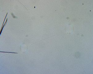
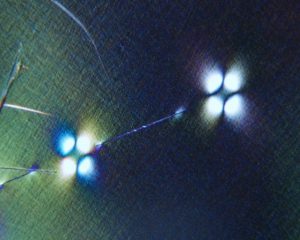
Here is an example with polarized light. The polarizing system has a polarizing filter in the base for the transmitted light, and that’s a fixed filter, and as the plane polarized light comes through the sample in transmitted light, up into the objective lens, then we have another filter above the objective lens that is a rotating polarizing film. Now we can rotate the analyzer, as it is called, and cross the polarizers. When we do that, we can now see various features. You can see in this image the foreign material that’s embedded in that polyethylene film on the left-hand side; you really can’t see much of anything in there.
But with the crossed polarizers, now we can see two very distinct features: these bright spots, if you will, that are emanating from something that’s in the center of them. Those bright spots are formed from strain birefringence in the polyethylene film. They will produce these strain patterns under crossed polarized light. So, now we can go into the center of each of those little clusters and find the foreign material and extract it out of there for analysis to find out what is.
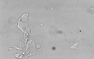
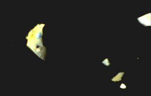
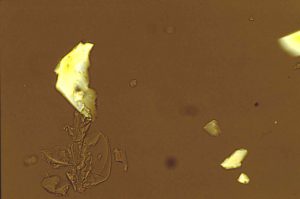
Here is another example of polarized light microscopy. If you’re looking at samples that have a lot of clear, crystalline materials in them, you can’t really tell too much about them or try to differentiate them with normal plane polarized transmitted light. They’re just clear fragments; you really can’t distinguish anything from one another if they happen to be different materials. One of the ways to help distinguish these types of things is to cross polarizers again. If we do that, now we can see that some of these fragments have coloration to them. These are known as the birefringence colors—the retardation colors of the crystalline materials due to different refractive indices and based on the orientation of the crystals. We can see in this image of the crossed polarizers that now the glass background becomes dark—black—and it becomes black because glass itself is amorphous. It has no crystallinity to it; therefore, it is not going to produce any of these colors. But also notice in the plane polarized transmitted light image, toward the lower left side of the big fragment, there is another group a little fragments that are invisible now under crossed polarizers. That’s the material that is known as isotropic material. It does not have the birefringence as the other crystalline materials do, and we can easily differentiate now the isotropic materials from the more crystalline materials, known as anisotropic materials in the samples.
We can also show both of them the same time if we slightly uncross the polarizers; in other words, rotate that analyzer plate just a little bit more beyond full cross. We can start to see, now, some of the isotropic materials along with the crystalline materials—the birefringent materials. Then you can start sorting things out that way as well, when trying to determine, say, relative quantities of isotropic material versus the birefringent materials—things like that.
Crossed polarizers again, this is an example from electrolytic tin-plated steel. Electrolytic tin-plated steel is usually fairly shiny, and bright, and smooth—kind of a silvery-looking appearance to it. When we look at it with a polarized light microscope under the crossed polarizers—this is reflected light crossed polarizers—we can see coloration differences. These coloration differences are due to the crystal orientations of the tin in the tin-plated surface. So, here in the center of the left-hand image, the tin crystal is a fairly large crystal, and has a tan appearance versus the more bluish coloration of crystals around it.
If we rotate the stage, 90°, keep the polarizers crossed, and rotate the stage 90°, now we see that the color shifts. Now the crystal is blue, and the surrounding area is tan. This is actually a technique that’s commonly referred to as optical staining. We know about staining various things with chemicals and so forth, but in this case we’re certainly not using any chemicals; we’re using optical properties of these crystals based on their orientation and what they look like under crossed polarizers, with the various colors based on their orientation.
Here are some more examples of that. This is a painted aluminum panel. It is a polished cross-section, metalographically polished to a nice smooth finish, a nice mirror finish, with a regular reflected light brightfield imaging mode. We can see in the paint, right in the middle where the green arrow is pointing to, that there is a small crack or fissure leading all the way from surface of the paint down to the base metal underneath, and that is a potential site for corrosion attack. Any liquid material that might be in contact with that paint surface can now migrate down through that crack and get to the aluminum underneath it and start corrosion mechanisms in place. These are defects—and in paint—that you definitely don’t want to have.
Now if we look at the same image in reflected light darkfield mode, we can now see the crack a little bit better, and it has a little more contrast to it. It’s a little darker compared to the white paint matrix. Also notice how the aluminum surface now looks very dark, and we can see all the fine scratches compared to the nice reflected bright surface in the brightfield image.
For those of you that do metallography work and polish cross sections like this, and you look at your cross-section visually, and you look at it under the microscope with brightfield-type illumination, and you think, “Aww that’s a beautifully smooth surface, mirror finish,” don’t ever look at it with darkfield then, because you’re going to see that all the little scratches and defects from your polishing compounds are highlighted very well. You can also use it, of course, as a quality control examination for your metallographic polishing: see how well you have really done.
Now if we look at it with reflected light in cross polarizers, we can see the aluminum a little better now. It is a grayer area underneath. The white paint is still white, and the crack is still visible, but not quite as visible as with the darkfield imaging.
If we look at it with reflected light in cross polarizers, and let’s insert into the light path above the objective lenses a filter known as a first-order red plate—it’s a retardation plate that retards light in the neighborhood of 550 nm, I believe. We have our rotating analyzer above that, leading toward the eyepiece. With that first-order red plate in place and a rotating analyzer, we can produce different colors—in this case, the aluminum now looks blue and the paint is still white, and we can see the crack still fairly easily. This is an optical staining-type technique with that rotating analyzer and the first-order red plate.
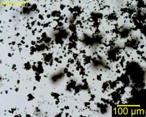
Here’s an interesting example of various lighting conditions on some white particles that are dispersed. In this particular dispersion they’re on the smooth black carbon tape, and these are carbon tape tabs that we often use for the scanning electron microscopes to mount samples onto just to adhere them in place, and use it that way. The black is from the carbon black that’s put into the tape to make it conductive.
In reflected light, under the microscope, a lot of these particles look pretty dark—they’re not white. they look very dark—and the reason for that is that these particles have tremendous topography variations. They are almost like crinkled raisins, if you will. So, now the reflected light going into those particles is going to be reflected in all kinds of different directions, not always back to the objective; certainly not one hundred percent of that light coming back to the objective and the eyepieces, so they are going to look dark.
If we go to oblique lighting on the same tape, we can now see that the tape is black, like we would expect it to look, and the particles are mostly white, or at least whiter, but there are still some that are fairly dark, even under the oblique lighting.
Let’s go take that white powder and disperse it onto a glass microscope slide and look at it with transmitted light and see what we find.
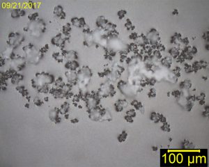
With the plane polarized transmitted light on the left, now these particles appear black against the nice white background—or light gray background—of glass. That means these particles are very opaque. They might be white, but they are also very opaque; not much light can get through them at all; that’s why they look black.
You note that if these particles were dispersed in a much finer monolayer type dispersion, the contrast of black against the white background would be really good to do particle sizing measurements with off-line particle sizing type software. You can take a bunch of images like that, and then collect the images into the software for the particle sizing.
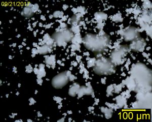
If we look at the particles, the same field of view with transmitted light and cross the polarizers again, we see now that the glass has turned black, which it should, and the particles have a light gray color to them. In polarized light microscopy with crossed polarizers like this, we’re actually looking at coloration due to birefringence of the material: some crystallinity. In this case, these particles, appear to have some very low-level crystallinity; the coloration of the light gray is known as first-order gray. As the refractive indices in various orientations were more spread out, more different, the colors would start to go into yellows, and reds ,and blues, and so forth. This is an indicator of the fairly low birefringence material, but it’s really not the true color of the material.
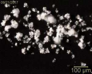
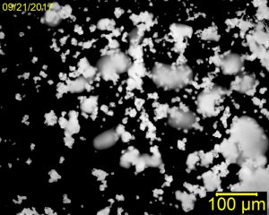
If we look at it in transmitted light again, just with darkfield—get the polarizers out of the way and look at it in standard darkfield illumination—we see that now the particles are white, and even the smaller ones now look quite light compared to the black background. Once again, these types of images with nice monolayer thin dispersion can be used for particle sizing of these types of materials.
Switching out to fluorescence lighting—this is an example of some just some general soil particles, looking at it with reflected light in the fluorescence mode. Fluorescence cubes are put into the microscope path—in the light path before going to the objectives—to transmit only specific wavelengths of light from the electromagnetic spectrum. In this case, for fluorescence imaging, typically the wavelength of the light sources are going to be ultraviolet or violet, near-ultraviolet, near-violet type of wavelengths to impinge down onto the samples through the objective lens. Then, the samples, typically, in soil like this, minerals, and various plant materials, have a natural fluorescence property where they will fluoresce the light back to the objective or to the eyepieces in the visible wavelength regions, so that we can see the various colors.
Now we can see that there’s a lot of different shades of green, blue and aqua perhaps, and in the left-hand image there is a nice bright yellow-orange particle sticking out at us. I know from experience that the calcite mineral, which is calcium carbonate, fluoresces an orange color under these conditions, so I suspect that that was the calcite mineral, although we didn’t analyze it.
On the right-hand side—the right-hand image, we have a kind of a U-shaped object there. That’s a nice bright blue, and that’s a synthetic fiber and it’s most likely mercerized cotton or linen to produce that type of a bright color under these conditions. Using these types of conditions one can go in and select specific materials based on their fluorescent colors, and sort them out and separate them for various analyses purposes.
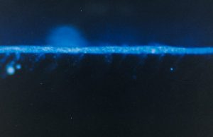
We can also use fluorescence microscopy for, let’s say, man-made things. There are dyes, known as chromoform dyes, that can be added to resins, for example. In this case, we can then use fluorescence microscopy for our examinations. In this particular case, it’s an automotive paint problem where the paint was failing adhesion very severely, to sheets of the paint coming off This was being done when Ford Motor Company was first developing the painting systems for the thermoplastic olefin bumpers and facia panels that are on cars today. They were having a terrible time with the paint adhering to the thermoplastic olefin, and we were able to help them out a little bit by making cross sections of some of these areas that had failed, and in polarized light microscopy, and I don’t have a picture of that, but we can see that there was some crystalline material right at the surface of the plastic. It turned out from some X-ray diffraction work that we did that the crystalline material was recrystallized polypropylene from the thermoplastic olefin, and that forms during the molding operation. So, the cure for that was to change the parameters in the molding operations to minimize and eliminate the formation of a polycrystalline polypropylene at the surface. So the dye, the chromoform dye, was added to the resin in the paint, in this particular paint it is used as what they called an adhesion promoter, like a primer coat. The purpose of it is to use the solvent carrier with the resin to penetrate down into the plastic surface to anchor it in place. If it cannot penetrate into the plastic surface then it’s not anchored properly and it loses adhesion.
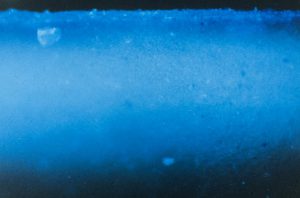
So in this case, in the top image, we have no penetration and that would be very bad. We were able to use the fluorescence microscope to look at cross sections of the samples that they submitted. These cross-sections were made by simple razor cuts, there’s nothing fancy about that. Just put it under the fluorescence microscope in reflectance mode and look at the colors.
At the bottom image we can see what’s known as the optimum penetration that they finally came up with. They did study of baking temperature/time of the adhesion promoter on the plastic to determine the different depths that they were getting, and we could easily give them that information very quickly. They finally decided that the 450 – 500 µm penetration depth was about optimized for their adhesion.
A lot of this information and work was published by Ford Motor Company, Dr. Rose Ryntz. She published a lot of this in the journal for the Federation of Societies of Coatings Technology, it is their technical journal published. There are several articles that were published on this if you’re interested.
Let’s go back to the plastic surfaces again. This is not paint; this is a plastic surface. Let’s look at the technique known as Nomarski differential interference contrast, or NDIC as the acronym is used. In the left-hand image we have standard reflected light brightfield mode, and we can see that there’s some features on the plastic, but certainly with the NDIC capabilities we see much more detailed surface features that stand out quite easily compared to just regular reflected light—producing an image or a view in the microscopes that one can go in there and start picking off or cutting out some of these materials for analyses.
Some more NDIC. This another polymer that had a lot of surface defects in place. In the regular reflected brightfield mode we can’t see anything, but with NDIC they are easily visible, and now again they can be isolated and brought out. There are different types of things here, right in the center of the field of view, we have an irregular shaped material embedded in there, there are some more off to the left-hand side of the image, and then we have a lot of these little circular knobs, if you will, that are probably different material that can be cut out.
NDIC again with a plastic surface where a paint was applied to it and failed miserably in little blotches. We couldn’t see anything on the surface of the plastic where it failed and we couldn’t see anything on the back side of the paint either under the microscopes. With NDIC we could see on the substrate that there was an oily film. In this specific image you really would not be able to tell if it’s an oily film or liquid film or if it is just the surface flattening of the features on it just from some kind of physical-mechanical force. But if you take a needle and while looking at this under the microscope, and just put the needle into that region little bit, and move a little bit, you can see that it’s actually liquid. Now, we can go in there and we can extract that material and take it out for mounting for infrared analysis to find out what that oily film was.
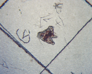
Here is some glass in NDIC. Under normal conditions, glass is very smooth, very little surface feature to it unless you have some dust on it, of course, but really clean it off well, the glass is usually very smooth and even with NDIC, you cannot see very much features or topography. But if there’s a physical defect embedded in the glass, NDIC is a really good way to see it. In the bottom image the area that’s labeled as “1” is the foreign material that’s embedded in the glass, kind of a yellowish color here. The other objects or features that are identified in rectangle number “2” are actually refractive index variations within the glass due to the presence of the physical defect that’s embedded in there with it.
That’s really the tip of the iceberg for imaging capabilities and illumination capabilities, and so forth, but I hope that gave you some thoughts on the how things can be done, and how you can improve things, and get different lighting conditions because you never know what you’re going to run into. Different lighting conditions can really reveal the true nature of the various things you are looking at.
For the microscopist out there that are really striving for perfection, this curse of lighting is absolutely unavoidable and is going to be costly, and you have to initiate these budgeting, battle plans really early to convince your management that this stuff is really going to be necessary. I wish you good luck and thank you for attending.
CZ: It looks like we have quite a few questions here Wayne. Can you explain how and why coaxial illumination creates such clear lighting when ring light does not?
WN: Okay, well the coaxial illumination is actually projecting two parallel beams of light down through the objective lens to the sample, and then it is reflecting back up into the eyepieces. That actually is a reflection techniques where it is reflecting off the surface in a two-dimensional plane, if you will, and it shows the surface as a reflection and kind of eliminates the color, I guess, if you will. It is more complex than that, of course, but that is the simplified explanation for it. The ring light is producing like a cone of light. Think about the perimeter of a cone coming down to the focus point on your sample, and it is illuminating at this focus point all the way around the entire field of view. So it’s really eliminating all of the shadowing effects with the ring light. That’s what makes it more difficult to see features on smoother surfaces when you’re using ring light for your illumination compared to the coaxial illumination.
CZ: Mark is asking if you can please refer to the slide of basic necessities. If you want to scroll all the way back there, we can check that out for a moment.
WN: There it is. Okay, those are the minimum requirements. Those are what I consider minimum requirements, anyway. Again, there’s more that you can add to stereomicroscope, but these are the ones that I use quite a bit.
CZ: Curtis asks, “Can you please describe an examination scheme safe for a visually smooth surface? What would be the sequence of lighting conditions for the exam? Would you use all lighting conditions for all sample types or certain ones for general categories of items?
WN: My typical answer to that is I like to use everything I have. Generally, for a smooth surface, I would look first of all with the coaxial illumination, that really highlights the features on the surfaces with a stereomicroscope. Now if you need to go to higher magnifications, then you would have to go to the compound microscope and set it up or something like the Nomarski differential interference contrast illumination, then you can see the fine detail on smooth surfaces.
CZ: Scott asks, is coaxial illumination significantly more expensive than ring lights or oblique lights?
WN: I don’t know.
CZ: You have to buy the box, the light source, for either one, and then it is a matter of plugging these things in…
WN: I would think they are more expensive.
CZ: …and then the attachment itself — that intermediate piece.
WN: I think that the best thing to do is to contact our McCrone Microscopes Accessories group, and they can give you more information about pricing. Certainly the oblique lighting, like I have, just the gooseneck light is probably the cheapest, for sure.
CZ: Shane, you say, “Why do we call things staining in light microscopy, as you said really is not staining?”
WN: Yeah, it is called optical staining, that is what we refer to it as over the years. It is called staining like that —that is kind of in quotes, because were changing colors. We’re manipulating colors based on how we rotate the filters in the microscope system. It’s a color change based on orientation of the crystals, orientation of the various filters that we are using in the light paths, and so forth to change colors.
CZ: Well, I think that might do it for the questions, Wayne. Thanks again for attending.
Comments
add comment