Developing a Coolpix® Adapter for the Olympus BH2
Articles in Royal Microscopical Society Proceedings article by Peter Evennett recommended in one of the “Micscape” articles, demonstrated how the Nikon Coolpix 990 was the best-suited consumer digital camera for use with microscopes. Its moderate aperture, internal zooming and focusing lens was found by others to permit recording the full field of view of a 10X eyepiece provided that the eyepiece or adapter has a high enough eyepoint. My prior publication in The Microscope (Clarke, T. M. “Digital Imaging in the Materials Engineering Laboratory”; The Microscope 1998, Vol. 46 No. 2, 85-100) on digital imaging in the materials engineering laboratory with a Kodak MegaPlus scientific-grade digital camera, has a composite image demonstrating how using a non-compensating relay lens in place of a compensating Kpl eyepiece in a Zeiss Universal can drastically degrade image quality. This is by chromatic difference of magnification (CDM), which is cancelled by the matching compensating eyepiece. [A description of this problem, and its origin may be found on p.11 of John Delly’s Kodak publication, Photography Through The Microscope (1)]. Part of this image is reprinted in my “Micscape” article on the effects of CDM. The “Micscape” articles led to my purchase of a later model Coolpix 995 for my modified LOMO and Monolux microscopes. My article Fitting a Student Microscope with a Consumer Digital Camera (see note 1) in Microscopy Today (May/June 2002,15-18) demonstrates the Coolpix camera mount I made for these microscopes. A 10X 20-mm field number high eyepoint eyepiece was purchased from Mark Simmons, a maker of digital camera adapters, for my Monolux using Edmund Scientific objectives not requiring a compensating eyepiece. This eyepiece has an eyepoint of about 23-mm, which I found adequate to prevent vignetting without having to nest the eyepiece into the filter threads of the Coolpix lens. I knew that my LOMO Edupointer eyepiece (no longer in production)had only an 18-mm eyepoint and was the highest-eyepoint compensating eyepiece for the LOMO objectives. This lower eyepoint distance required the eyepiece to be nested inside the filter threads in order to avoid vignetting.
My first use of the Coolpix 995 with an Olympus BH2 was to help Peter Cooke ( of MICA, Chicago) record images of high-resolution dispersion staining with the Olympus 40X objective. This photography was done using the Coolpix 995 mounted in a salvaged enlarger stand so the 10X WHK eyepiece in the trinocular photo port was almost in contact with the end of the filter threads of the Coolpix lens. Vignetting could not be prevented, even though the camera aperture was manually set to the smallest f/number to minimize vignetting caused by the camera iris, so the resulting images were cropped. The camera lens was not zoomed to exclude the vignetted outer zone because I know this could introduce image artifacts from residual tool marks on the mold surface subsequently replicated on a molded plastic aspherical lens element in the Coolpix lens. The experience helping Peter led me to suspect that the vignetting could be reduced with an 8X WHK eyepiece because of its smaller angular field. Chuck Zona of McCrone Microscopes and Accessories subsequently provided me with an 8X WHK eyepiece to determine whether a suitable adapter could be made for the BH2 using this eyepiece. This took place after sharing e-mails with him from an environmental microscopist. This microscopist was upset over the poor image quality of his digital images taken with a BH2 microscope and Coolpix 995 using a non-compensating adapter purchased on a recommendation from one of the teachers of digital microscopy. The making of the BH2adapter with the WHK eyepiece and its subsequent modifications to fit a Coolpix 990 are the subject of this article, with emphasis on the lathe-threading process used for this adapter.
The Coolpix 4500 was the last in the series of swivel body Coolpix cameras using the lens design making them uniquely well suited for use with a high eyepoint eyepiece. These cameras are no longer in production, but there should be a good supply of used and refurbished 990, 995 and 4500 models for those wanting low cost, high resolution digital imaging with a BH2 microscope.
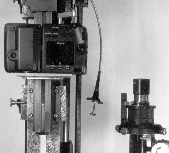
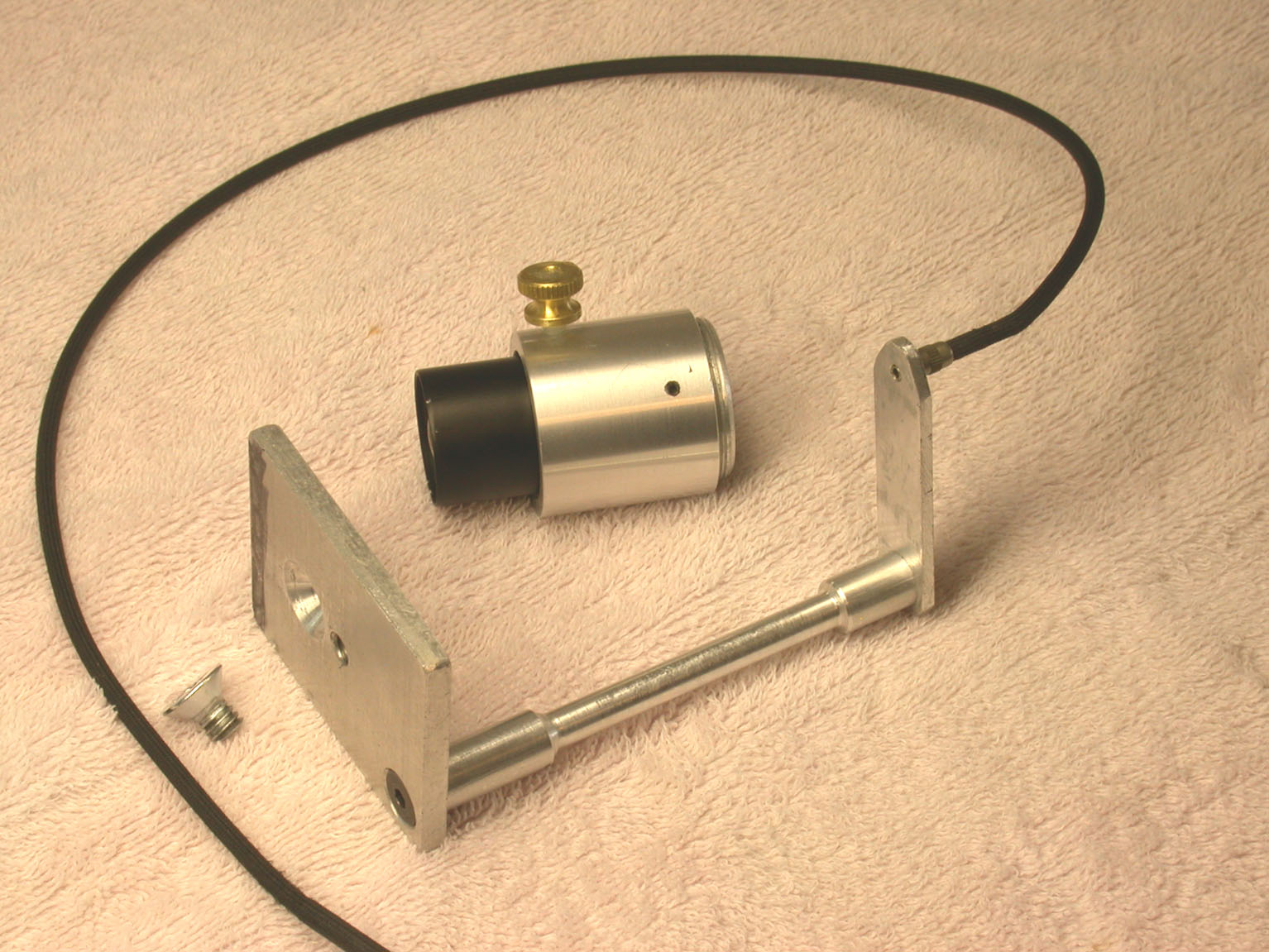
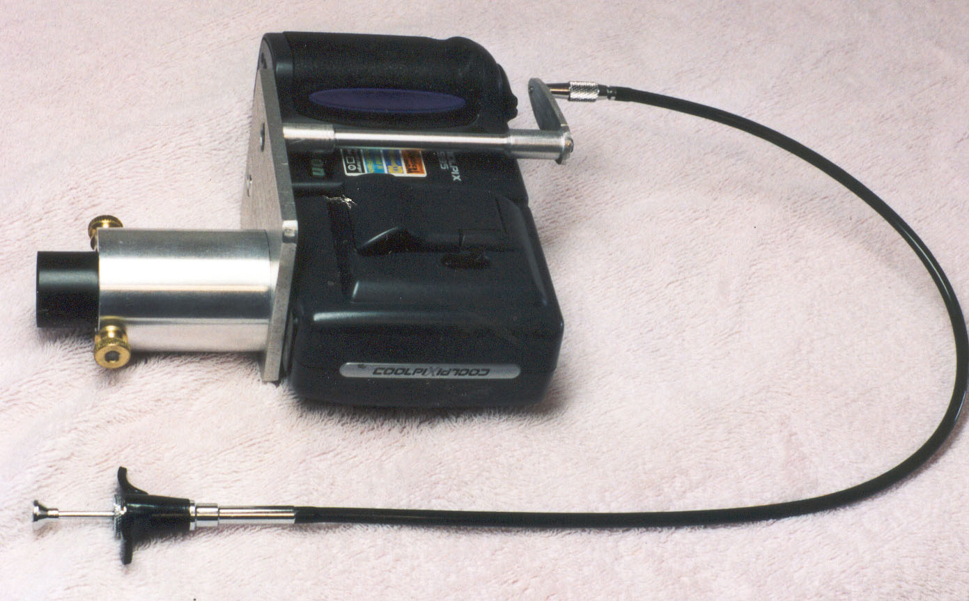
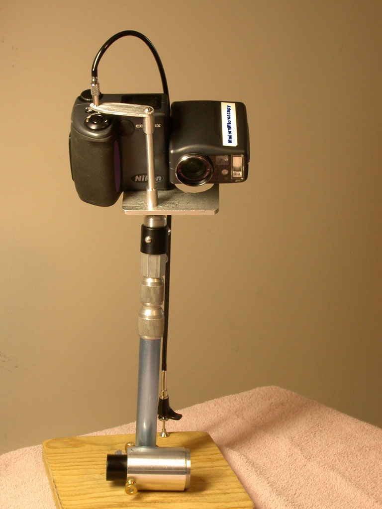
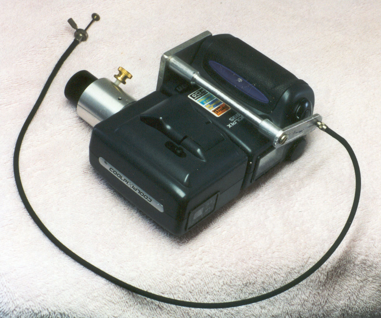
The Zeiss compensating eyepiece had to be nested inside the 28-mm filter threads of the Coolpix lens to eliminate vignetting, but the cover cap on the end of this eyepiece was already 28-mm in diameter. I had no choice but to cut threads into the cover cap for direct mounting to the Coolpix lens. The mechanical cable release was built into a separate base, which attaches to the tripod-mounting hole in the camera base as shown in Figure 4.My initial tests of the Olympus 8X WHK eyepiece were with the Coolpix 995 mounted separately on my macro stand as shown in Figure 1. My procedure is to first focus through the high eyepoint eyepiece visually. Then I slide the microscope under the camera for digital imaging as shown in Figure 2, with the eyepiece just clearing the filter threads on the camera lens. I set the camera focus at infinity because the autofocus does work reliably with the camera used on a microscope. I manually set the camera aperture to the smallest f/number to minimize vignetting by the camera iris.
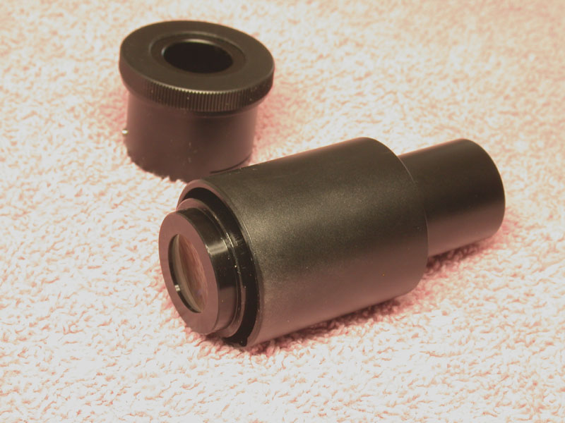
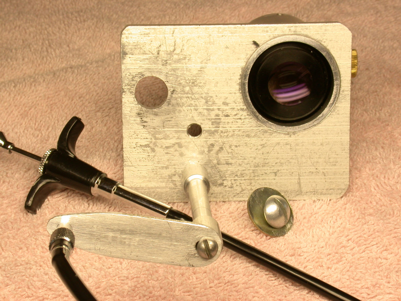
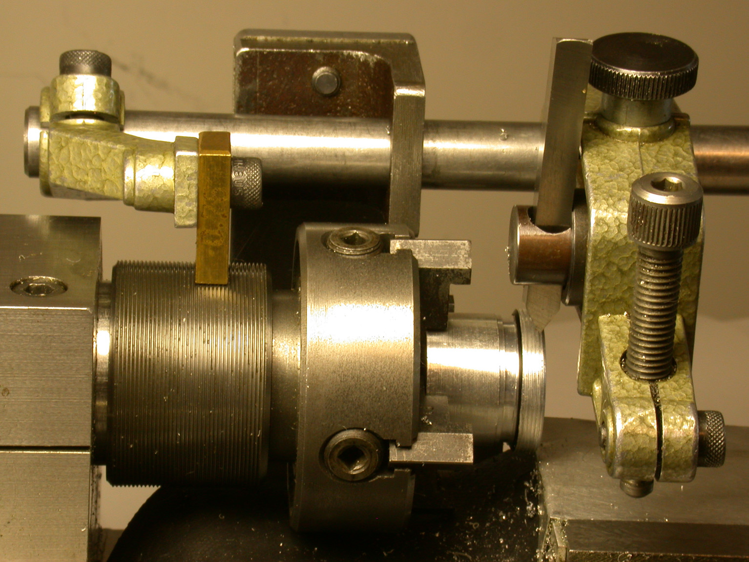
I used this procedure with the 8X WHK eyepiece and found that there was a small amount of vignetting at the edge of the visual field. This meant that the eyepiece would have to be nested inside the filter threads to eliminate the vignetting. This step was also necessary with the adapter I had previously made for my LOMO Biolam microscope. Fortunately the eye-shield on the WHK eyepiece is easily removed as shown in Figure 3. The end diameter of the eyepiece is now small enough to nest inside the Coolpix lens threads. My preference in adapter design is to attach the adapters to the tripod-mounting hole in the camera base instead of directly to the filter threads. The step in diameters with the eye-shield removed made this design quite easily done. This was not the case for the adapter I made at about the same time for a Zeiss Universal microscope.

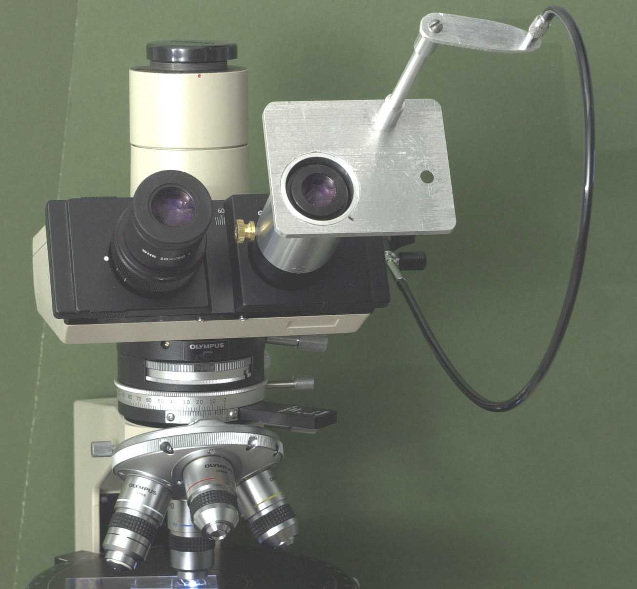
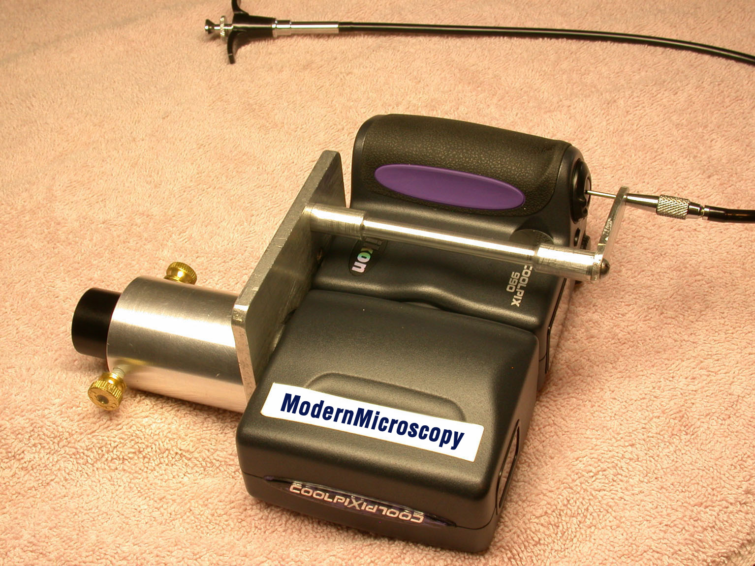
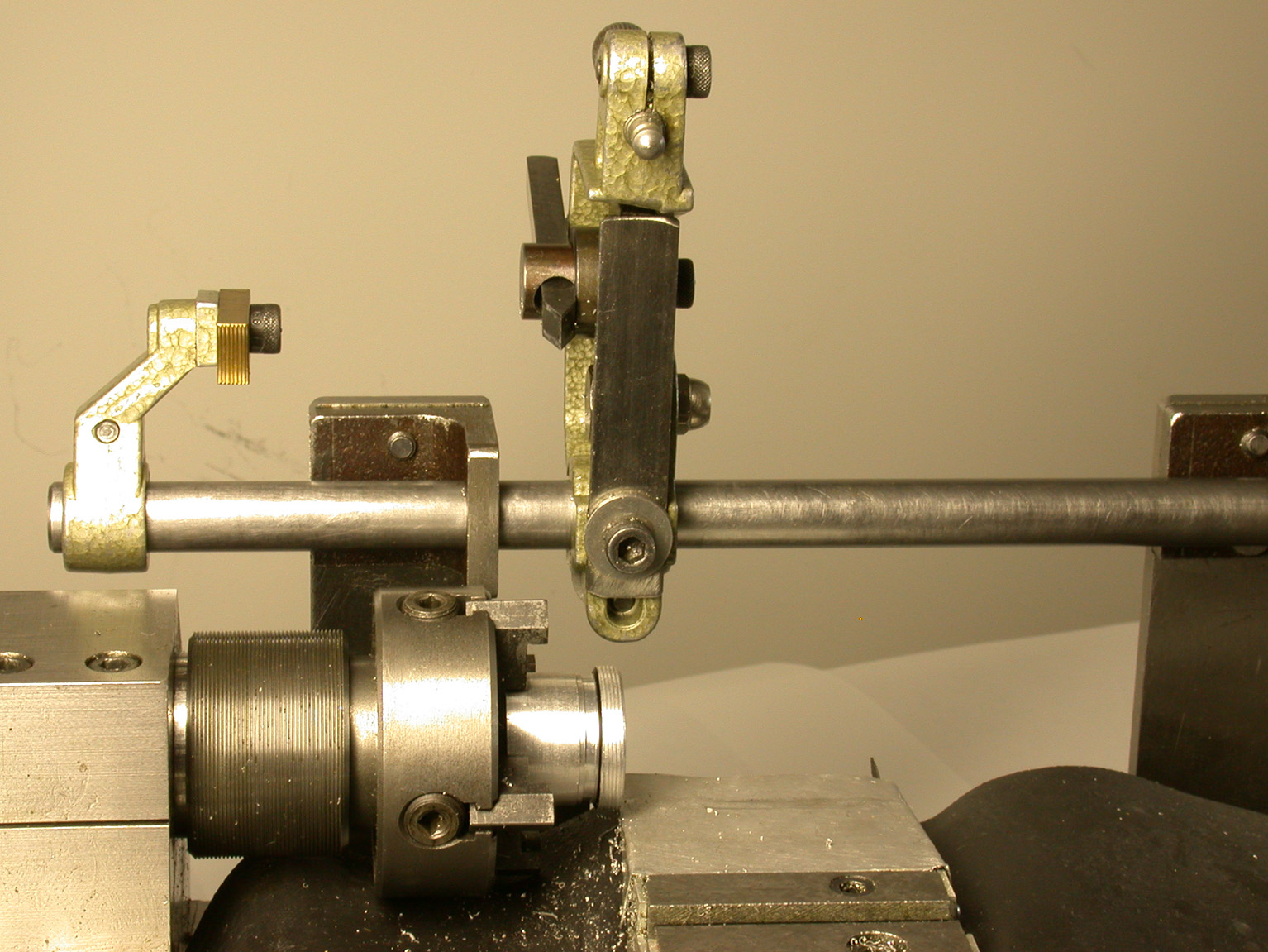
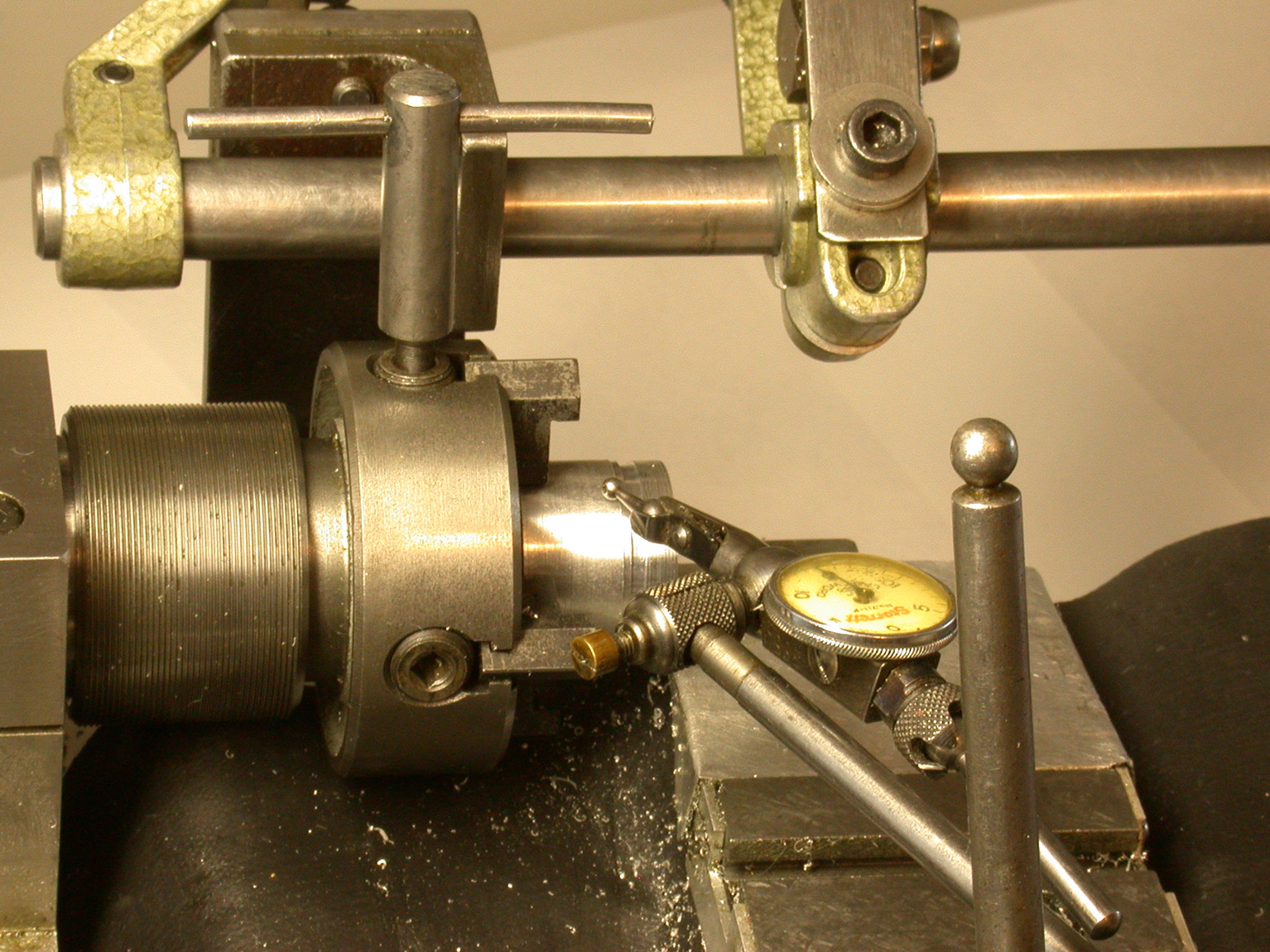
The design chosen for the BH2 adapter is similar to that used for the LOMO Biolam and shown in the Microscopy Today article. The major change in design was to thread the end of the bushing for the eyepiece and the mating flat base instead of attaching to the flat base with screws through a flange on the end of the bushing. Another change was to properly locate the shaft for the cable release so there is no interference with access to the DC power cable port of the camera. The first adapter I made had to have a notch cut into the side of this shaft to clear the power cable. The bushing has an internal shoulder to locate the end of the eyepiece 1 mm from the glass face of the Coolpix lens. The other end of the bushing fits over the right eyepiece tube of the BH2 and is locked with two nylon thumbscrews as shown in Figure 5. This initial design fits my Coolpix 995 shown in Figure 6. A Coolpix 990 camera was loaned to me to determine whether it would also fit the adapter. It did not because the lens location was moved off the centerline of the camera base in the transition from the 990 to the subsequent 995 model. The adapter was modified to fit both camera models.
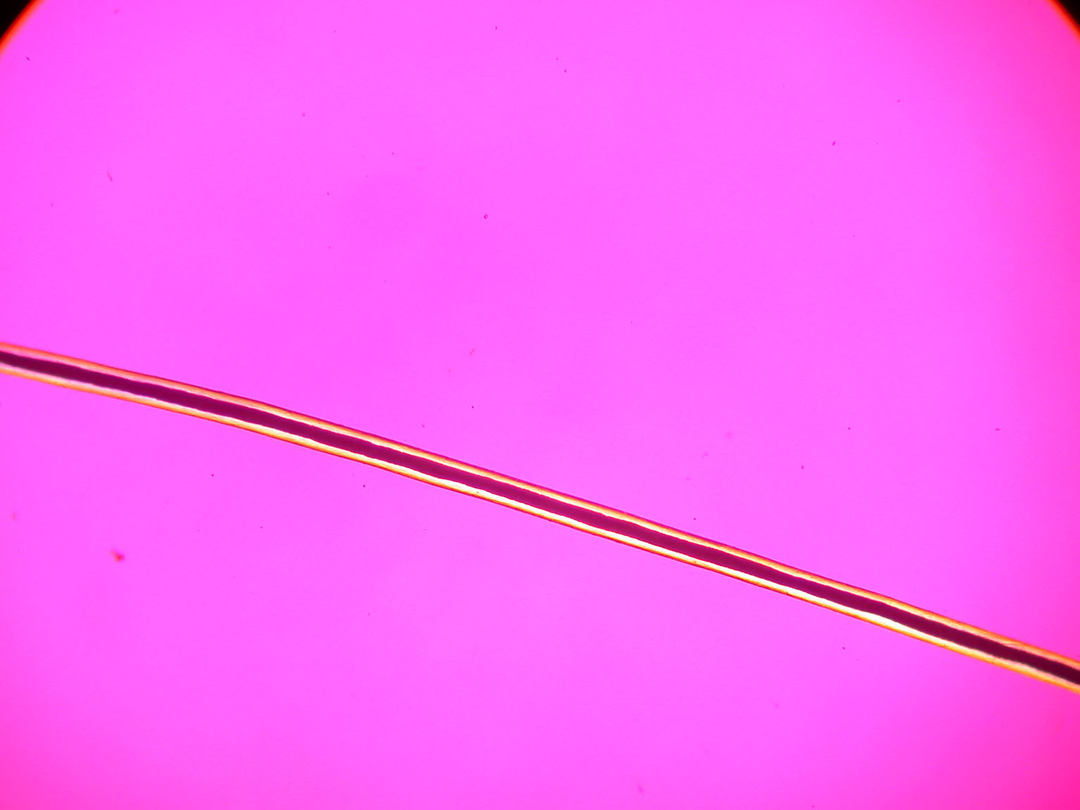
This was done by greatly enlarging the hole for the tripod mounting screw. The camera base is first squared up by rotating the camera about its lens extension, which fits into the end of the bushing in the base as shown in Figure 7. A round-headed ¼”-20 screw to the tripod mounting hole in the camera base is now used along with a large-diameter fender washer spanning the gaps around the hole when the screw is tightened. The #6-32 screw mounting the cable release arm to the shaft now passes through a slot in the arm so the cable release can be centered over the shutter release of either the 990 or 995 camera. Figure 8 shows the 990 mounted in the adapter. I have since learned that the location of the tripod hole has been relocated in the change from the 995 to the 4500, the final camera model in this series. The BH2 adapter would probably fit the 4500 with an additional hole added through the base to mate with the relocated tripod hole. The real performance test for the BH2 adapter came at the Inter/Micro 2003 McCrone Microscopes and Accessories exhibit, where the adapter was mounted with my Coolpix 995 on an Olympus microscope using 160-mm tube length objectives. The photomicrographs in Figures 9 and 10 were taken of fiber samples. The 20 mm field number (diameter of opening in eyepiece diaphragm) stop in the adapter eyepiece shows in the upper corners of Figure 9, which demonstrates no vignetting or ring artifacts from the camera lens. Vignetting may occur if the camera aperture is not manually set to the smallest f/number. The image of the edge of the stop has an orange color fringe characteristic of a compensating eyepiece. Note that Figure 10 was taken with the camera lens zoomed just enough to put the field stop outside the field recorded.
Another very important capability of the Coolpix 990, 995, and 4500 model series is the ability to be used in macro mode with a minimum field width of 21-mm, for my Coolpix 995. The threaded bushing containing the 8X WHK eyepiece can be quickly unscrewed from the adapter, as shown in Figure 11, so that the camera can be mounted on a monopod while retaining the cable release feature of the adapter. The flat base of the adapter has a ¼”-20 threaded hole for attaching to the monopod or tripod shown in Figure 7.


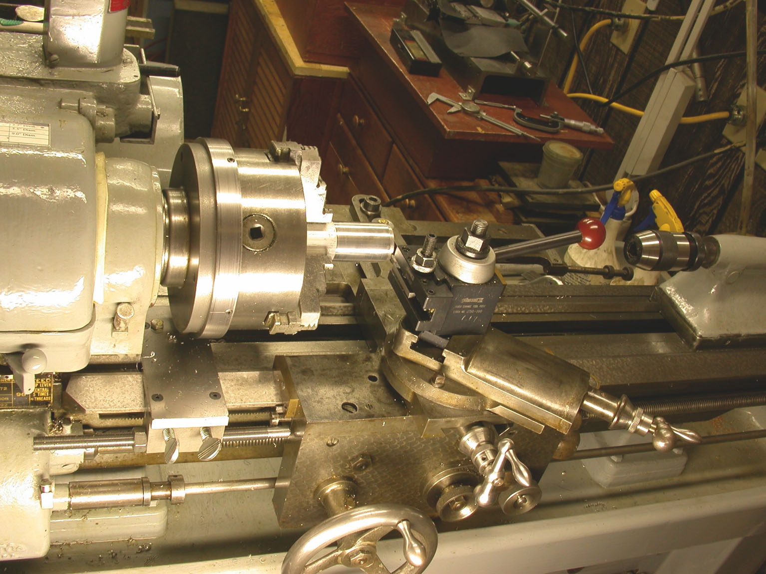
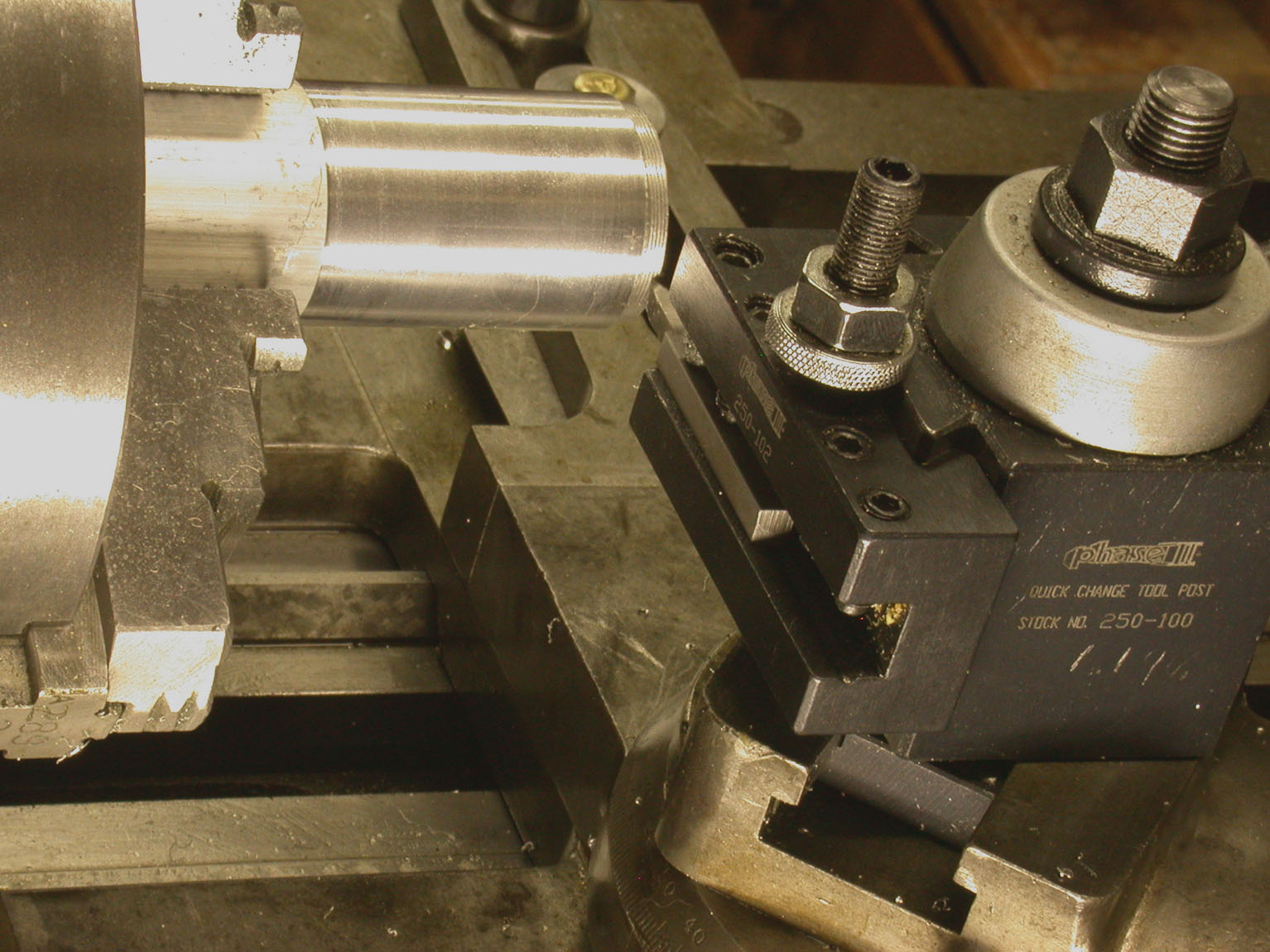
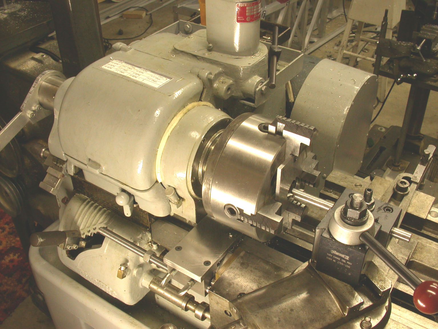
The half nut on the lead screw is left engaged until the threading operation is completed. This avoids the mistake of not engaging the half nut at the proper setting of the threading dial, and actually speeds up the process. Figure 13 shows the cutting tool engaged in the threads with an adjustable stop for the cross slide to allow quick and accurate return to the same setting before taking the next threading pass after moving the 60 degree included angle cutting point inward with a small increment of feed from the compound set at a 29 or 30 degree angle. This is shown close-up in Figure 14. A thread pitch of 40 threads per inch was chosen for the adapter. Cutting of the mating internal threads in the flat base is shown in Figures 15 and 16. The cutting point for this operation is set in the end of a boring bar.This final section is for those interested in how the threads were lathe cut for the connection between the bushing and flat base. Lathe cutting of threads is a procedure most home machinists try to avoid. The bushing has only a short section of threads ending at a shoulder. This makes an accidental and disastrous collision of the cutting tool with the shoulder very likely. The quick change gear box on my Wade lathe makes the setup time for the threading operation minimal compared with the time which would be required for machining a mounting flange on the end of the bushing and locating and tapping the holes screws through the flange into the flat base. The solution to the risk of collision with the shoulder has been known for a long time and generally ignored because it is not a method used by production machinists. One solution, discovered by others, is to disengage the motor drive and drive the lathe with a hand crank as shown in Figure 12. This photo shows an adjustable stop for the carriage to prevent cutting into the shoulder at the ends of the threads. This would not be safe to use under conventional threading with the motor drive because the gear drive could be damaged if the half nut was not disengaged just before the carriage reached the stop. The hand drive with the crank allows adaptive control of the loading on the crank as the carriage reaches the stop. The cutting tool is backed out of the threads and the crank rotation reversed after the stop is reached.
My Wade lathe cannot cut metric pitch threads. The Coolpix lens filter threads have a pitch of 0.75-mm. I can cut metric threads with my modified Unimat miniature lathe. I had to cut the 0.75-mm pitch threads in the cover cap for the Zeiss Kpl eyepiece using the Unimat system. I also use a hand crank to drive the Unimat spindle for thread cutting. The Unimat uses an unusual method of cutting threads without a geared lead screw used on conventional lathes like my Wade lathe. A thread pattern attaches to the spindle behind the work-holding chuck. The cutting tool with its cutting depth control mechanism is mounted on a sliding rod along with a brass follower, which engages with the thread pattern behind the chuck as shown in Figure 17. Threading the cover cap for the Zeiss eyepiece to fit the Coolpix threads required first making a mandrel with 0.5-mm pitch threads to mate with the internal threads of the cap. This threaded mandrel is shown in Figure 18 while it is being centered in the four-jaw chuck before the cap is installed on it for external threading. Figure 19 shows the external threads being cut into the cap. The Zeiss adapter is shown fitted to my Coolpix 995 in Figure 20. The time to do the threading of the Zeiss eyepiece cap with the Unimat was far greater than that needed for the BH2 adapter.

REFERENCES
(1) Delly, John Gustav (1988). Photography Through the Microscope. Eastman Kodak Company Publication P-2, Ninth Edition. Eastman Kodak Company, Rochester, New York.
NOTE
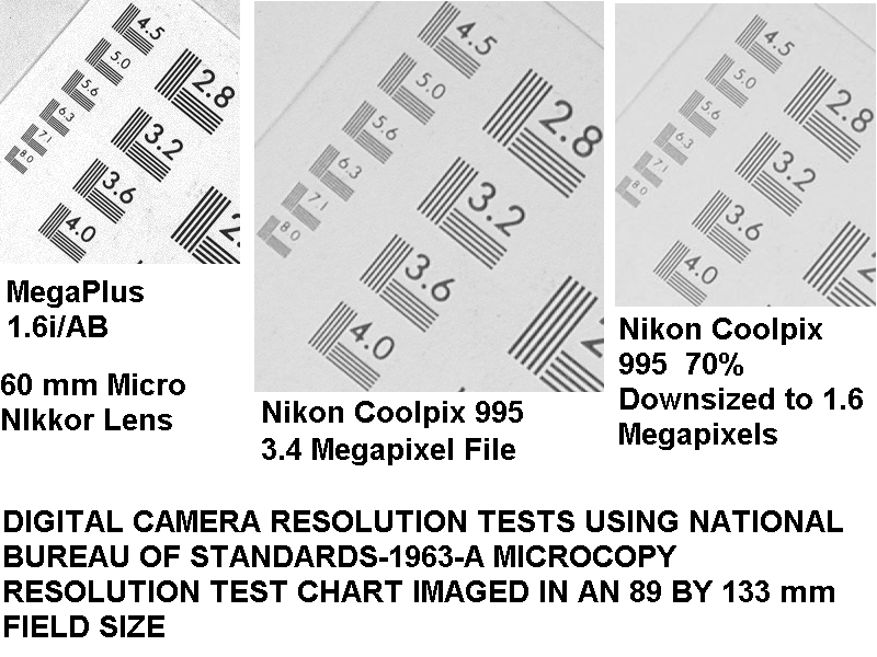
(1) Fitting a Student Microscope with a Consumer Digital Camera – Figure 8: Resolution Test (below), demonstrates that a digital camera with a Bayer color filter mosaic sensor requires about twice the number of pixels to achieve the same spatial resolution as a monochrome camera using a filter wheel or tunable liquid crystal filter for sequential capture of the image in three primary colors. Re-sampling the Bayer array image with Adobe PhotoShop using the bi-cubic method allows the number of pixels to be cut in half without significant effect on spatial resolution.
Comments
add comment