Confessions of a Light Microscopist: An Afternoon with Mr. Footswitch
The Confessions of a Light Microscopist series are stories about individuals who take their microscopy craft to the highest possible level—laboring over the smallest details, and leaving no stone unturned. This confession comes from a person that I’ll call Mr. Footswitch—let’s see what he has to teach us.
The Confession: “When using my stereomicroscope and polarized light microscope, I employ a series of foot switches to activate my light sources, allowing me to never take my eyes or hands off of the sample while directing the light to the specimen where needed. I simply press my foot down on the appropriate foot switch when I need to activate a particular light source.”
His justification for using a series of integrated foot switches with his microscope is analogous to a guitar player trying to achieve different sound effects with a foot pedal while their hands are both occupied playing music. In all my years of speaking with microscopists, I have never actually seen anyone use a foot switch in practice. To get a better understanding of what a microscopical analysis looks like using a foot switch, Mr. Footswitch invited me out to his lab to show me his setup. However, and perhaps as his way of making this a teachable moment, he asked that I first collect a suitable sample for analysis. He recommended that I go to the neighborhood street curb and collect a “gutter” sample. It was this sample that we would examine with the microscope, employing the appropriate foot switch during the analysis. But before we get to the analysis, let’s take a look at what equipment you will need.
Making the Switch to a Foot Switch
To get started, you will need to purchase two common foot switches, the first is known technically as double pole single throw (DPST), which means press the foot switch once (click) and it stays ON, press it again (click) and the foot switch turns OFF. This foot switch is used for the transmitted light source on your microscope. The other foot switch is called momentary contact—push down on the pedal to turn it ON (no click), remove your foot to turn it OFF (no click). For this one, think of a sewing machine foot pedal. When integrated with your microscope’s light sources, these two foot switches will allow you to activate your reflected light, and/or transmitted light lamp housings, individually or simultaneously with a simple depression of each foot. But which foot, the right or left? Well actually, using these two foot switches requires the use of both feet. Your left foot controls the momentary contact foot switch, and is used for your reflected light illuminator, while the right foot controls the DPST footswitch, which operates your transmitted light source.
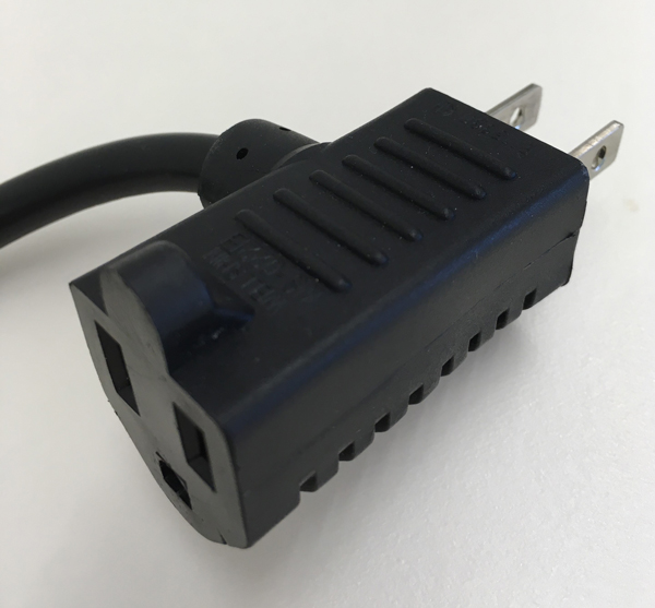
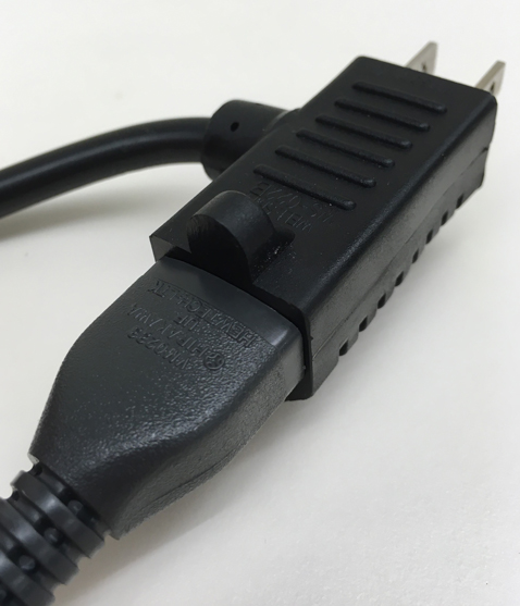
Next, as you might expect, you simply begin plugging in each of the power cords from your light sources into the corresponding foot switch receptacle, and then plug the foot switch into a standard power strip.
Click on any gallery image to enlarge.

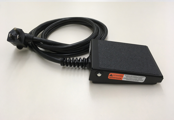
You can purchase these two types of foot switches at just about any home improvement store, or online. The cost for both the DPST foot switch and the momentary contact foot switch was around twenty dollars each. There didn’t seem to be much variation in the quality between foot switches, but there are a couple of things to be on the lookout for when purchasing a foot switch. I found that having a rough textured non-slip base on the bottom of the foot switch, the part that comes into contact with the floor, acts as an anti-slip feature and was helpful in preventing the foot switch from moving along the floor when trying to engage it, especially on tile. Other features to note are the weight of the foot switch; having some weight to it also helps prevent it from moving, and optional screw holes on each side of the pedal are nice, in case you want to secure the foot switch to the floor with screws.
Curbside Particle Pickup
The image below is of the street entrance to The McCrone Group and is the site where I collected my curb sample. Mr. Foot switch said that a curb sample was a great one to begin with, because we could expect to find many different types of particles that were also in various states of environmental degradation. He also pointed out, in a Sherlock Holmes kind of way, that we might find different types of particles deposited at the east curb versus the west curb because the prevailing wind in our area is west to east.

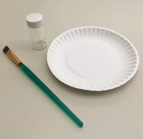
Once you collect your first curb sample you will never look at curbs the same way again. After collecting my sample, I began to notice the debris gathered at curbs while on walks in my neighborhood, and while driving down the road. Some spots will have an incredible amount of debris. And that’s what I encountered at 850 Pasquinelli Drive. Initially, I thought I could collect the curb sample using a small jar or vial with the help of a small paint brush and a 6” disposable plate. As I approached the curb, I soon realized that I would need to increase the size of my collection tools and container. The amount of debris at our curb was substantial.

You can see that this curb sample contained a significant amount of pine needles and other large items like whole insects, large pieces of plastics, and gravel. For this curb sample collection, I used a 4” × 6” plastic box with a hinged lid. I called this Curb Sample #1.

As I panned-out, so to speak, from what I will call the primary curb, indicated by the blue arrow below, there was a secondary curb, a much shallower depression containing comparatively finer debris, indicated by the red arrow. I labeled this material Curb Sample #2.

The finer debris could be collected with my originally intended sample collection tools, a small paint brush to push the material onto a 6” disposable plate, and then into a wide mouth glass vial.
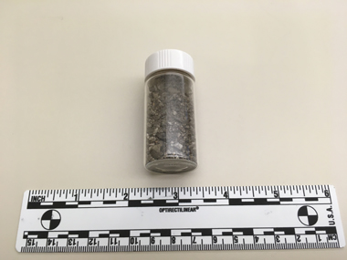
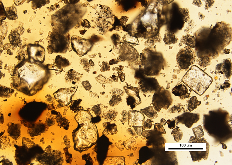
The contents of the jar were then transferred to a weighing boat, and first examined at low magnification using a stereomicroscope. A small amount of sample was removed from the weighing boat and prepared for a higher magnification analysis using a polarized light microscope. The mounting medium used was Meltmount™ 1.662.
As Mr. Footswitch said initially, a curb sample will always contain a wide variety of environmental particles ranging in appearance from transparent, to translucent, to opaque. These observations are common because the particles have been exposed to a number of weathering factors including acid rain, changes in temperature, and ultraviolet light degradation. He said that particle degradation will be presented microscopically as a continuum affecting a particle’s texture, color, opacity, and other physical and optical identifying features. For example, rubber particles shed from automobile tires are typically found in curb samples, and exhibit a range of elastomeric properties depending on the degree of UV light degradation.
Soon after I handed over the prepared curb samples, I began to hear clicking sounds coming from beneath Mr. Footswitch’s work area. I noticed a corresponding turning on and off of the light sources on his microscope. He began to comment on the composition of the sample, describing tree, weed and grass pollen, various minerals, mold spores, botanical fragments, and insect parts. He mentioned yellow and white particles of lane marker paint, and also the presence of significant amounts of power plant fly ash. Using a magnet, he was able to quickly determine the magnetic particles mixed-in with the sample. He also pointed out the importance of focusing all the way through the preparation in order to find less dense particles that had floated to the top of the mounting medium during sample preparation, and could be found just beneath the coverglass.
Keeping Your Undivided Attention
At this point, you may be saying to yourself, “Is there a real advantage to using a foot switch? Can’t I just reach over and flip on my fiber-optic gooseneck to see what color my opaque particles are?” And the answer would be, yes, you could. But what I’ve noticed in using foot switches myself, especially with an extremely heterogeneous sample like the one from the curb, is that every time I had to take my eyes off of the sample to find my light source switches, my attention was broken. With each glance away from my sample, I had to reset my concentration, it felt like an interruption to my thinking, kind of like your email inbox dinging at you while you’re trying to read an article online.
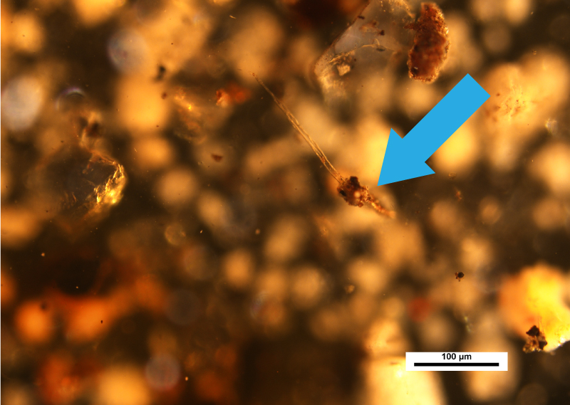
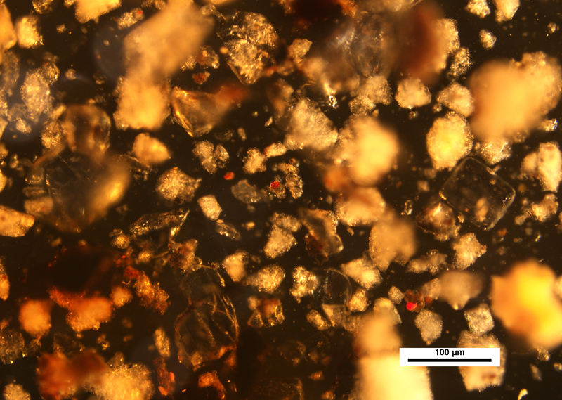
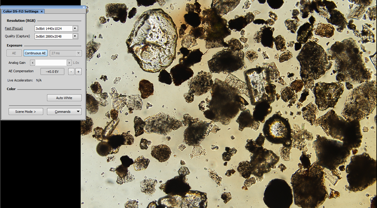
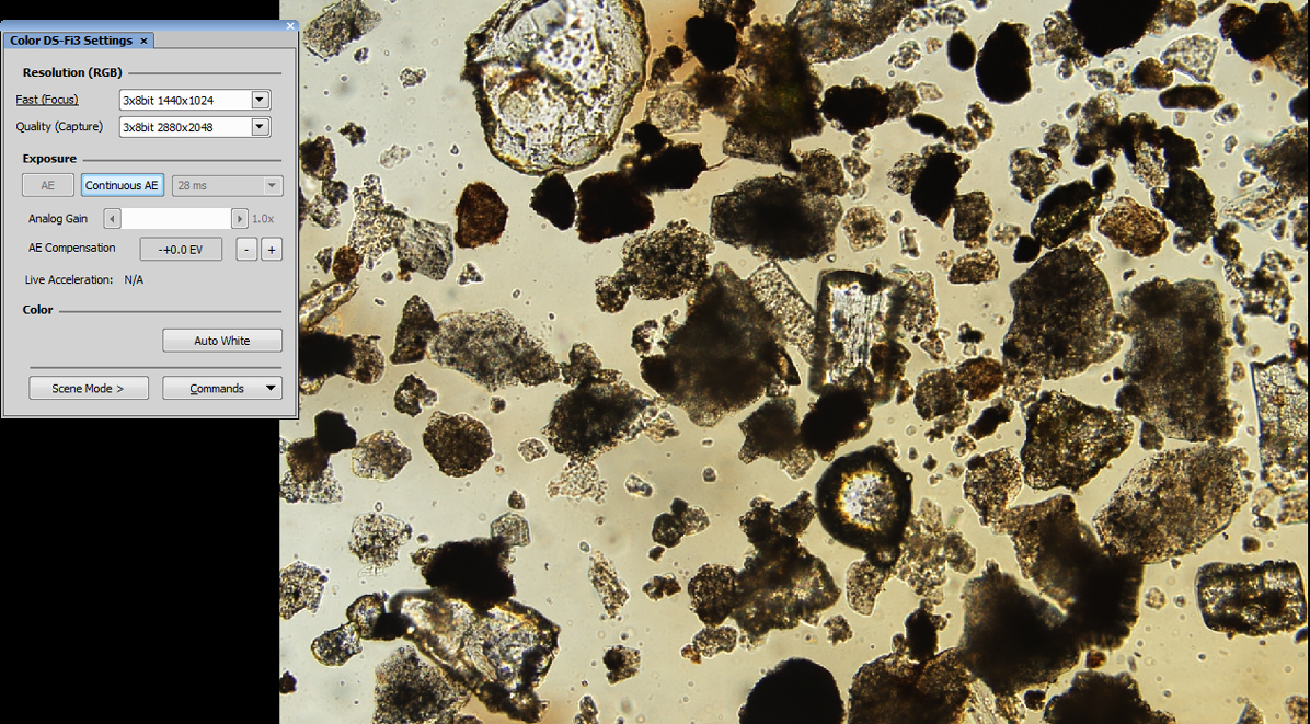
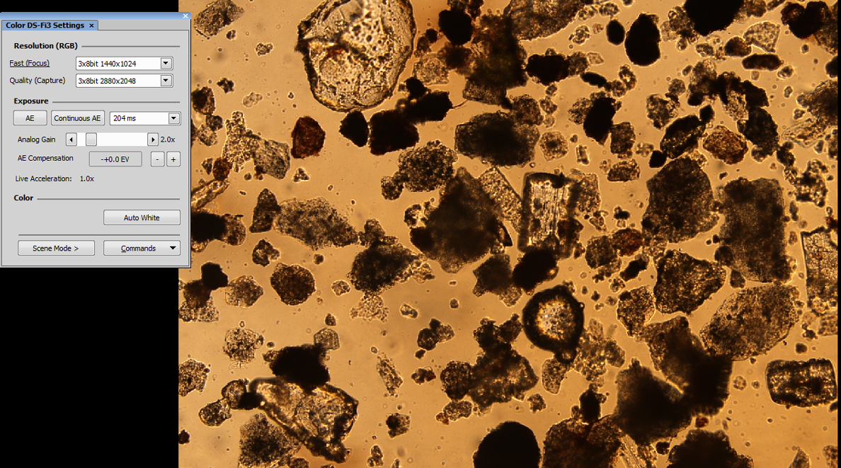
The images below are from Curb Sample #2. As most of you know, what appear as opaque particles in transmitted light many times reveal that they are colored when viewed with reflected light.
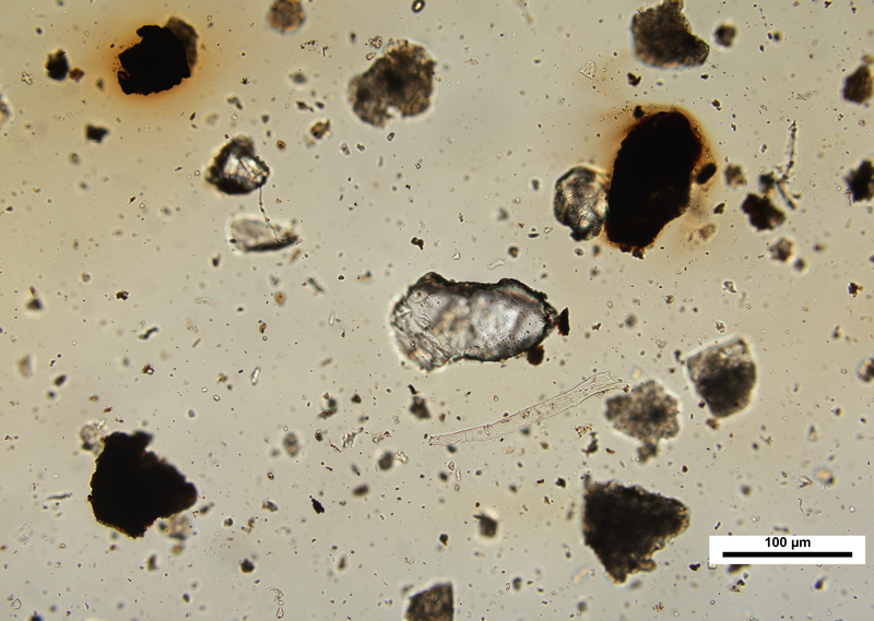
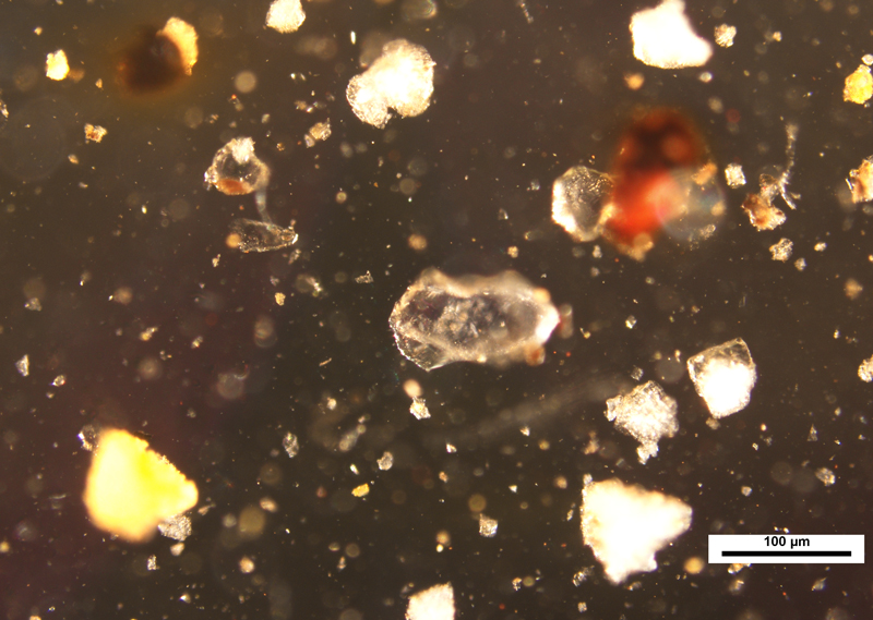
Also, as mentioned earlier, the set of images below point out particles in the same field of view that have floated to the top of the preparation, indicated by the blue arrow. This illustrates the importance of optically focusing through the sample.
One other interesting observation that was made during our examination of the curb sample was the bleeding of some of the asphalt material into the surrounding Meltmount. You can see this in the image at the very top of this article. What first appears as uneven and warm illumination on the left side of the image, is actually material that has dissolved into the mounting medium. If you take a look at the lower right corner of the image, you can see the transition of color from yellow (upper left) to what is the true neutral background (lower right).
Adjusting the Color Temperature “Thermostat” on Your Light Source
As I marveled at the practice of using the foot-switches on his microscope, Mr. Footswitch seemed to recognize that perhaps I was more intrigued by the operations of the light sources with his feet rather than what was coming out of the light sources themselves. He said, “Using a foot switch…In a sense is worthless if one doesn’t consider the composition of the actual light coming from the light source itself.” So I asked him to explain.
“When it comes to the color temperature of your microscope’s light source, few people seem to take notice. Most people just hit the capture button and live with images that are either too yellow (warm) or too blue (cold).”
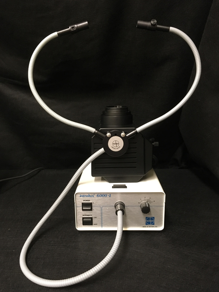
This is something that I have been paying more attention to in my own work when evaluating a field of view before capturing any photomicrographs. The key, of course, is to have the proper color temperature filtration on your light sources, making sure to white balance and black balance the camera, and turn off any overhead room lights. Since I use an Olympus BX51 polarized light microscope, I use the daylight blue filter that comes standard with the microscope at the 9 volt setting. The Volpi fiber optic illuminator that I use for my reflected light setup does not come with a daylight blue filter. You have to purchase the daylight filter separately—which I highly recommend—in order to achieve proper daylight conditions.
With regard to color temperature, Mr. Footswitch had this last piece of advice. In setting up your microscope for Köhler illumination, he recommends that you focus the field diaphragm slightly to the blue rather than the yellow. What exactly does this mean? Well, the next time you set up your microscope for Köhler illumination (which should be every time you change the slide preparation), you will notice that when you are focusing the image of the field diaphragm, either a yellow halo or a blue halo will appear at best focus, around the closed down image of the diaphragm. Then focus the field diaphragm ever-so-slightly to favor the blue because it is closer to daylight, which is the ideal color temperature not only for photomicrographs, but also for your brain, as the brain physiologically prefers this color over the harsher yellow color produced from a tungsten or tungsten-halogen light source. I have to say, I did not see that one coming.


Managing Your Current Affairs
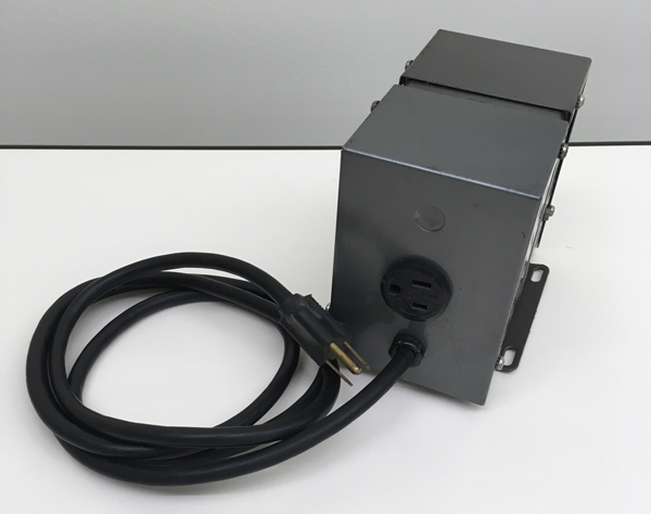
In the discussion above we mentioned that you can simply plug each foot switch into a standard power strip. However, during my visit with Mr. Footswitch, I noticed a small nondescript gray metal box sitting on the floor near his foot switches. When asked what the gray box was for Mr. Footswitch said, “It‘s a constant voltage transformer,” which he recommends be used to ensure that an unfluctuating constant voltage is supplied to all of your benchtop electrical components, which includes your light sources. The constant voltage transformer is plugged into the wall socket and then a power strip is plugged into the constant voltage transformer.

It was explained to me that operating your light sources at a constant voltage will eliminate the risk of the user experiencing a change in color temperature as a result of a drop or spike in voltage to your light source, which would alter the color temperature of any images that you capture. We tested this idea by first plugging our microscope light sources into what is known as a VARIAC. A VARIAC is a type of transformer that allows you to control the output voltage going into any device requiring electricity. The VARIAC we used has a voltage output range of 0-140V, and can be easily adjusted manually by turning an indicator dial to a desired voltage. We used the VARIAC to simulate a drop in line voltage to our Olympus BX51 polarized light microscope. We noticed that dropping the line voltage to our BX51 had no effect on the light intensity of the microscope. Of course once we dropped the voltage significantly, the light at the microscope began to dim.

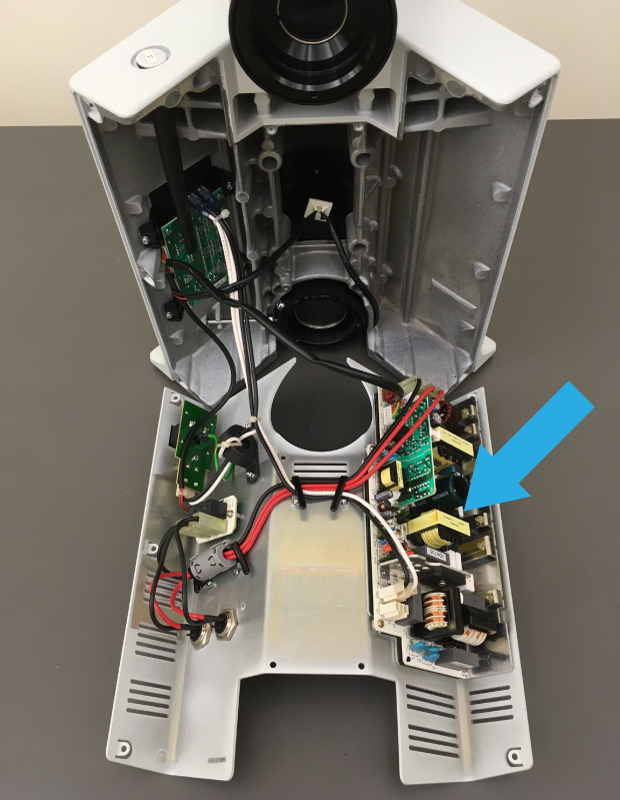
Our microscope was able to maintain its light output even under conditions of significantly decreased line voltages, because the BX51 has a constant voltage transformer built into the electronics located inside the base of the microscope. This was also true for the Olympus SZX10 stereomicroscope. The picture below shows the internal electronics of the Olympus BX51 microscope, the constant voltage transformer is indicated by the blue arrow.
It appeared that there was no need to use a constant voltage transformer, at least with a modern compound microscope or stereomicroscope. However, when we ran the same test using the VARIAC on a modern fiber optic illuminator, the drop-off in light intensity was immediate. As the line voltage to the fiber optic illuminator was decreased, we noticed an immediate corresponding decrease in light intensity. By removing the outside metal cover of the fiber optic illuminator and taking a look inside, there was no constant voltage transformer to be found. So in cases where you might be using a fiber optic or a light source that has no means in compensating for a drop in voltage, you may want to consider using an external constant voltage transformer to maintain the proper line voltage to the unit.
Customizing Your Light Guides
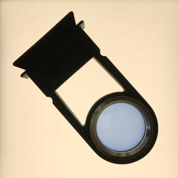
In taking a closer look at Mr. Footswitch’s microscope, I noticed that he had customized the attachment for his fiber optic light guides. The two attached light guides were terminated by a fairly long flexible lead running to the light box, which is pretty standard, but he had attached the two light guides to the underside of his reflected light lamp housing—definitely not standard issue. This allowed for a perfectly symmetrical positioning of the light guides on either side of the specimen, producing even illumination when needed.
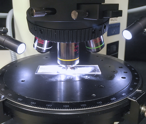
Most microscopists have no choice but to position the fiber optic unit and light guide off to one side of the microscope because of a shallow table depth, or if the table depth is sufficient, the fiber optic light guides are not long enough to reach directly from the back of the microscope all the way to the stage. The more common “off to the side” configuration makes it impossible to get both light guides positioned equally on each side of the specimen.
Attaching fiber optic light guides to the underside of a reflected light lamp housing is a fairly straightforward project. It was obvious that Mr. Footswitch knew his way around the microscope, but he also happened to be a master machinist, specializing in micro-machining. Of course! To attach the fiber optic light-guide, you simply drill two small holes in the bottom of the reflected light lamp housing, and two corresponding small holes at the base of the light guide housing, and then attach the light guides with some small screws.
As my afternoon with Mr. Footswitch was coming to an end, I began to realize how useful and elegant it is to employ foot switches to control the light sources on your microscope. In the beginning I was skeptical that using foot switches could be so important when using the microscope, but once you start using foot switches with a sample like those I collected from the street curb, you quickly realize how beneficial they are, not constantly glancing away from your sample in order to activate an illuminator is a real plus! These seemingly small interruptions add up over a professional life time, making for longer and more stressful analyses. Like our other confessions, once you see it in practice, why wouldn’t you take this extra measure? It’s easy to implement and relatively inexpensive.
On your next trip to the home improvement store, make sure to bring a small container with you and collect the debris from one of the curbs in the parking lot. Then go inside the store and buy yourself some foot switches to integrate with your microscope. You’ll soon see how easy it is to use foot switches, and that the curb debris, which up until now seemed to blend into the background of your day, will tell you an interesting story through the particles contained within.
Other articles in the Confessions of a Light Microscopist series:
The Man in Black
A Chemical Romance
Comments
add comment