Assembling Stereo Anaglyph Images with Photoshop
A recent article that appeared in Microscopy Today showed a flawed and very awkward procedure for using Adobe Photoshop® to combine stereo pair images into a color anaglyph that can be viewed through colored glasses. The correct procedure is quite simple and straightforward, as described below. The specific commands and functions shown correspond to all recent versions of Photoshop, on either a Macintosh or Windows PC.
The starting point is, of course, a pair of stereo images. Whether these are acquired with an electron microscope, a macro camera or by aerial photography, the basic requirements are that they be taken at the same magnification, be the same size, and that they include as much common area of the specimen as possible. If the two images are taken by shifting the camera or specimen laterally, which is the method often used at low magnifications or in aerial photos, the horizontal shift should not be more than about 15% of the image width. If tilting the specimen is used, angles in the 5 to 10 degree range produce good results. Using too large a shift or tilt may still produce images that are suitable for measurement of vertical heights, but the anaglyph image will usually have too much displacement of features (parallax) for comfortable viewing. In either case, the images must be viewed so that the shifts produced by tilt or rotation are horizontal, corresponding to a vertical orientation for the tilt axis or a horizontal shift for the displacement method.
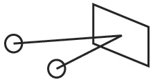
As shown in Figure 1, stereo viewing produces information about the relative depth of features in the image when the viewer’s eyes rotate inward in their sockets to focus on an object. It is only by rapidly shifting the point of focus among many locations in a scene that we build up a general mental map of the relative distances of objects by stereopsis. In most scenes it is other clues – relative size or position, rate of motion in the visual field, shading, the obscuring of one object by another, etc. – that provide most of the information on distance, which is why people with one eye, or who for various reasons cannot fuse stereo images, can still function well, drive cars, even play sports. When different images are provided to each eye, vision must select the same object in both images. If the points are displaced vertically, it becomes very difficult for the eyes to find them in the two different images. Also, large differences in contrast or brightness should be avoided.
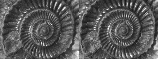
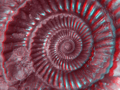
To assemble the stereo images into an anaglyph, open both of them in Photoshop. The example shown in Figure 2 is a stereo pair of a small fossil (an ammonite) using a macro camera, stopped down to get enough depth of field to keep the surface in focus. The fossil was mounted on modeling clay and tilted to get the required two views. The object was shifted to bring a recognizable location near the center to approximately the center of the field of view.
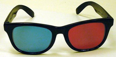
All colored stereo viewing glasses use the convention that the left eye has a red filter while the right eye uses blue or green. In case you didn’t save the cheap cardboard glasses they handed out when your local theater showed its most recent stereo thrill-a-rama (the enthusiasm for stereo movies seems to revive about every 10 years), you can purchase them easily. SPI Supplies sells good quality ones with real frames (Figure 3) for about $10, and both they and many other suppliers (don’t forget eBay) will sell you a dozen of the cardboard kind for that amount.
If the original images are in color, rather than gray scale, they must first be converted. This method of stereo viewing presents a monochrome image to each eye. (To view colored stereo images, other methods are used such as projectors and glasses with filters, or LCD lenses that can flicker on and off at a rate that corresponds to the screen display, or an optical viewer that directs different images to each eye.) Some people with experience in viewing stereo can just stare at the side-by-side images and achieve fusion. This article is directed toward the anaglyph method, which practically speaking restricts the images to monochrome. In Photoshop, selecting Image->Mode->Grayscale will remove any color information from the image and leave just the brightness or luminance information.
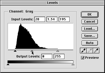
Depending on the nature of the image, you may want to make some adjustments so that the gray scale images have good contrast and brightness. This can usually be done satisfactorily using the Image->Adjustments->Levels function, by setting the black and white limits and the medium gray slider on the histogram (Figure 4). If more complex adjustments are needed, the Image->Adjustments->Curves function provides additional control. Remember that the two images should end up with similar brightness and contrast for the easiest viewing of the resulting anaglyph composite. This is also the time to apply any image processing, such as sharpening the detail contrast with an unsharp mask (Filter->Sharpen->Unsharp Mask), if desired.
It does not matter whether the images are 8 bit or 16 bit. Recent versions of Photoshop (CS and CS2, also known as Photoshop 8 and 9) can perform copy/paste operations, adjustments, and channel operations on either. But for viewing or printing anaglyph images there is no advantage to the greater bit depth after any adjustments to the images have been made, and the resulting file will be smaller if 8 bits is used. You can convert a 16 bit image to 8 bits by selecting Image->Mode->8 bits/channel.
Having carried out all of the preliminaries, the assembly process is quick and straightforward. Make sure that the left eye image is the active image (in Photoshop the title bar will be colored or highlighted). Choose Select->All (the keyboard shortcut is Command/Control-A) and Edit->Copy shortcut Command/Control-C). This places the image onto the clipboard. Now make the right eye image the active one by clicking on it. This is presently a gray scale image, but the anaglyph requires color. So convert the image to color (Image->Mode->RGB Color). The appearance on screen will not change, but the image now consists of three identical red, green and blue color channels. Make sure that the “Channels” palette is open (if not, select Window->Channels) click on the name of the Red channel as shown in Figure 5. That selects that channel as the location where the image on the clipboard can be pasted (Edit->Paste, or the keyboard shortcut Command/Control-V).
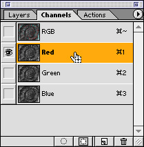
You have now assembled the anaglyph. To see it, click on the eye symbol for the RGB display (Figure 6). That will show all of the channels, with the left eye image that you pasted into the composite in red, while the original right eye image remains in the blue and green channels. Using both blue and green produces a cyan color for the right eye image that works well with all stereo viewing glasses and also prints better and brighter than just using one of the two channels.

If the images are perfectly aligned, you are finished. But in many cases, there will be some slight vertical displacement between the two images that should be corrected, or you may want to shift one horizontally with respect to the other so that the offsets are and the viewing is easier (this can also affect the impression of depth in the final result). Because the Red channel is still selected from the step above, even though all of the channels are being viewed (through your stereo glasses), you can now shift the Red channel (the left eye image) by either dragging it with the mouse or (usually more convenient) using the arrow keys on your keyboard. Each press of the key shifts the image by one pixel. If you depress the shift key the motion is ten pixels.
If it is also necessary to correct for slight rotational differences between the images you can select Edit->Transform->Rotate at this time. It is possible to use the mouse to grab a handle on the frame around the image and drag it, but in most cases it is easier and more controllable to enter numeric values into the tool bar (Figure 7). Note that in this bar you can also enter shifts, including fractional pixel amounts, and alter the size of the image in the horizontal and vertical directions. Changing the horizontal scale should be done with great care, as it will directly alter the parallax displacements and thus the stereo depth information. If the two images are not actually at the same magnification, the best procedure is to adjust the vertical scale of the red channel (the left eye image) to match the features in the right, and then use the same value for the horizontal scale.

Once the images have been aligned, you may find that shifting the red image has left some parts of the composite image in which the red image no longer covers the cyan one. You can eliminate the extra area by selecting Image->Crop. Then save the final result (with a different filename) and you are finished. This image can be viewed on screen, printed, etc. You may find that some adjustments to the overall image brightness or gamma produce optimum viewing, and that these will be different for viewing the image on screen, pasting it into a Word file or Powerpoint presentation (which will in general not preserve the contrast and brightness) projecting it, or printing it on paper (which also may depend on the type of printer used).
Figure 8 shows the result in this example. As a side benefit of the color anaglyph method, when viewing the image on screen, you can use the Channels palette to show just the left or right eye images (click on the name of the corresponding color channel) and to switch back and forth rapidly between them to show the image displacement due to shift or rotation. It is also possible to turn off either the green or blue channel (click on the corresponding eye icon) if you want just red/green or red/blue.


Comments
add comment