Making Antique-Inspired Microscopes Slides: The Wood Sliders
In this article and future articles, we shall share with you the techniques for creating a variety of antique-inspired microscopical preparations. We begin with one of the earliest types of microscope slides, the “wood slider”, as they were first called.
From the Stab to the Slider
In the early days of microscopy, it was common for the specimen to be fixed to a needle just in front of the viewing lens. John Mayall, in a series of lectures on the history of the microscope known as the “Cantor Lectures”, refers to the early needle-type specimen holder as the “stab”:
“The carrier…served to hold pointed or forked rods on which objects were fixed, the rod’s socket that now carries the “stab” and it would then serve as a stage for minerals.”
This method of specimen preparation is temporary; once the specimen is fixed and viewed, it must be removed from the needle to view the next sample. There is little chance of ever going back to the original specimen without damaging it or losing it altogether.

In Brian Bracegirdle’s book A History of Microtechnique, he describes the problem of specimen permanence this way:
“No preparations from the seventeenth century have survived, for it is almost certain that all were only of a temporary kind, for viewing on one occasion only…If the specimen was solid, it was simply glued to the point of a needle…if the specimen was liquid, it was spread on thin glass or mica, which was then glued to a needle.”
If the microscope user wished to establish a collection of microscopical objects to revisit later, a more permanent form of sample preparation had to be developed. In the late 1600s, the microscope “slider” made its first appearance, and was made from bone, wood, or ivory.

The slider’s construction as described by Brian Bracegirdle is straightforward:
“…hardwood sliders having several apertures each containing a pair of mica discs retained against a shoulder by a brass circlip.”
A typical microscope slider is between 1/8” to 1/16” thick and can have between four and six cells, each containing a transparent microscopical object held between two discs of mica.
The term “slider” comes from the practice of the user pushing or sliding the microscopical preparations, starting with the beveled end, through what’s called a spring table, first developed by Filippo Bonanni in 1691.

The microscope slider is held in place by the pressure from the spring table and then nudged along its travel by the user to reveal the next specimen in the slider’s cell. The yellow arrows below mark the spring table.

Which Way is Up?
When using a microscope slider, it should be used with the brass circlip facing down, toward the stage. Andrew Pritchard gives us a succinct description of its use in the final chapter of his book The Microscopic Cabinet, published in 1832, under the heading “Mounting transparent objects”:
“In using these sliders, like everything else, there is a wrong and right side, which must be observed, or the student will not be able to approach close enough to the object with the high powers. The ring side should always be placed downwards, or from the microscope, and the other side next the eye or instrument.”
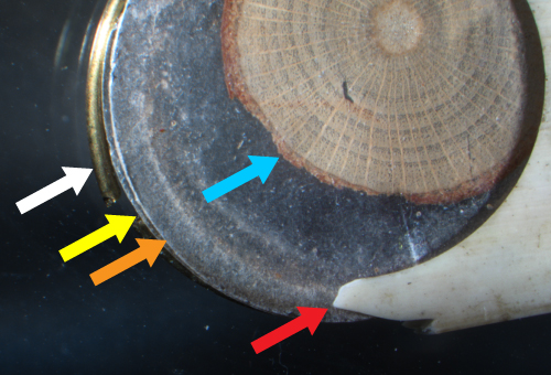
The image below is of a broken ivory slider, which nicely illustrates the four main elements of a slider’s construction, in a sort of cross-sectional view from what is the bottom of the slider to the top: first, the brass circlip (white arrow) resting below the first sheet of mica (yellow arrow), then the specimen (blue arrow) followed by the second sheet of mica (orange arrow), and finally the ivory shoulder (red arrow).
Again, a quote from Bracegirdle on the basic design of a common slider and its essential elements (emphasis ours in bold):
“Some very comprehensive sets of objects were supplied, in universal form of ivory or hardwood sliders having several apertures each containing a pair of mica discs retained against a shoulder by a brass circlip.”
Bracegirdle’s mention of the shoulder feature of the slider became a bit of a mystery to us. The literature doesn’t address how a slider’s shoulder is made.
In Frederic Kitton’s piece The Microscope and Microscopic Work, published in the 1876 Hardwicke’s Science Gossip, Kitton refers to the slider’s shoulder in woodworking terms as a narrow rabbet:
“The bottom of the cell had a narrow rabbet to prevent the small disc of talc upon which the object was placed from falling through; a second disc of talc was used as a cover and secured in its place by a split ring.”
From a woodworker’s perspective, the slider’s shoulder can be easily made today with what is called a Forstner bit, invented by Benjamin Forstner in 1886, but since ivory and wood microscope sliders were manufactured well before Forstner’s invention, how was such a feature achieved?
Perhaps the methods used to make wood and ivory microscope sliders were proprietary to the opticians who made them.
Drawing A Blank
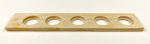
Our experiments to determine what type of wood to use for our sliders began with large wooden tongue depressors made from pine. A single tongue depressor is half the thickness of a typical wood slider, so we had to glue two of them together to make up the thickness difference. This also afforded us the opportunity to drill two different diameter holes in each tongue depressor, creating the slider’s shoulder. The image below shows the bottom tongue depressor with 14 mm holes glued to the top tongue depressor with slightly larger 15 mm holes.
This design provided an inexpensive and straightforward method for constructing a wood slider, but the softness of the pine made it difficult to form clean cell edges, and the tongue depressors were inconsistent in flatness and tended to warp over time.
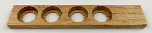
After our tongue depressor experiment, we realized a couple of things: using a single piece of hardwood would be easier to machine, and a template would be needed for a more uniform spacing of the slider’s cells. A slider template was drawn in Microsoft PowerPoint closely resembling the dimensions of one of our vintage wood sliders.

The template was printed on paper then cut out and placed on a wood blank, serving as a guide for creating the individual slider cells on the drill press. Each of the cell center points was marked with a pencil on the blank. The template was removed, leaving behind the pencil markings, and the wood blank was placed on the drill press.
Using a 15 mm Forstner drill bit, the depth of the drill press was set so the bit passed three-quarters of the way through the wood blank, followed by a second 14 mm standard drill bit to pass completely through the blank, leaving behind a 1 mm wide shoulder.
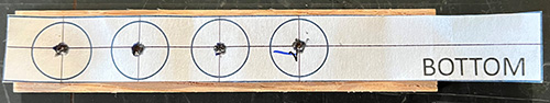
Below is an image showing the progression of the drilling process starting with the pencil target dot on the left.

Going Deep Into the Woods
The only clue from the literature of wood type to use for our microscope sliders was a quote by George Adams from his book Micrographia Illustrata. Adams references a way to preserve opaque microscopical specimens on what might be described as ivory and wood coverslips rather than sliders:
“And the very best Way of preserving opake objects…is to prepare small thin Slips of Ivory, or rather Holly, about an Inch long, and 1/10 of an inch wide…”
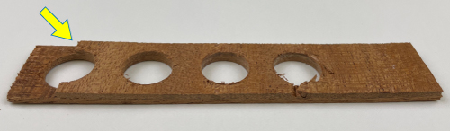
With not much historical information to go on, we set out to find an affordable, easy-to-machine wood source, and began with the purchase of 1/16” mahogany wood veneers. The veneers are roughly the same starting thickness of a wood slider. Upon drilling, the veneers were prone to what’s called “tear-out” indicated by the yellow arrow.
Not wanting to give up on the idea of using the wood veneer, we decided to glue three sections of the veneer together in an alternating stack ninety degrees from one another, and then cut the entire piece to size. The thicker substrate was more stable during machining but continued to produce unacceptable rough-edged cells.

With the success of the better-performing three-piece wood veneer, we moved to a thicker hardwood material, a ¾” thick piece of oak board. The oak was cut to length (99 mm) and then ripped to a height of ¼”. The oak board was then cut to length and width using a table saw.
Once the cells were drilled, the entire piece was sanded down to 1/8” thick.
Happy with the stability of the thicker oak blank, we still wanted to experiment; a 1/16” oak blank was made to see how it held up under the drill. The thinner oak blank remained stable during machining and produced smooth cell shoulders and edges. The image below shows both the 1/8” and 1/16” thick wood sliders.

The final woodworking step was the creation of the fifteen-degree bevel on the top side of the slider. This was done using a belt sander. The beveled lead edge allows the user to easily slide the wood slider into the spring stage. From the Brooks Collection, we have seen examples of sliders where the bevel appears on both ends, and on both the top and bottom.

Mica Sheets
With the slider’s cells made, it was time to fabricate the mica sheets that would hold our microscopical samples. Bulk pieces of mica were purchased from Emerald Village. The bulk sheets of mica were separated by hand into short stacks and then cut to size using a 15 mm hollow punch by striking the hollow punch with a hammer.
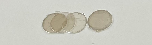
These stacks of mica sheets were then separated into thinner sheets by using a scalpel blade to start the separation and then finishing with a gloved hand; this reduces the possibility of scratching the mica.
Brass Wire
The broken ivory slider described earlier allowed us to measure the diameter of the circlip using a micrometer. The ivory slider circlip measured approximately 0.6” in diameter, which corresponds to a 22-gauge wire. Brass wire comes in three varieties: dead-soft, half-hard, and full-hard. The dead-soft and half-hard varieties are commonly used for jewelry making because of their pliable properties. Finding a full-hard version in a 22-gauge diameter proved difficult, so we purchased a 12” length of the half-hard brass wire from Wire Jewelry.
To form the circlips, the 12” length of brass wire was wound around a ½” slotted wooden dowel rod. The slot is used to hold one end of the wire while the remaining portion is wound around the wood dowel. The brass coil was then cut into individual circlips using a pair of wire cutters.


Prep Time
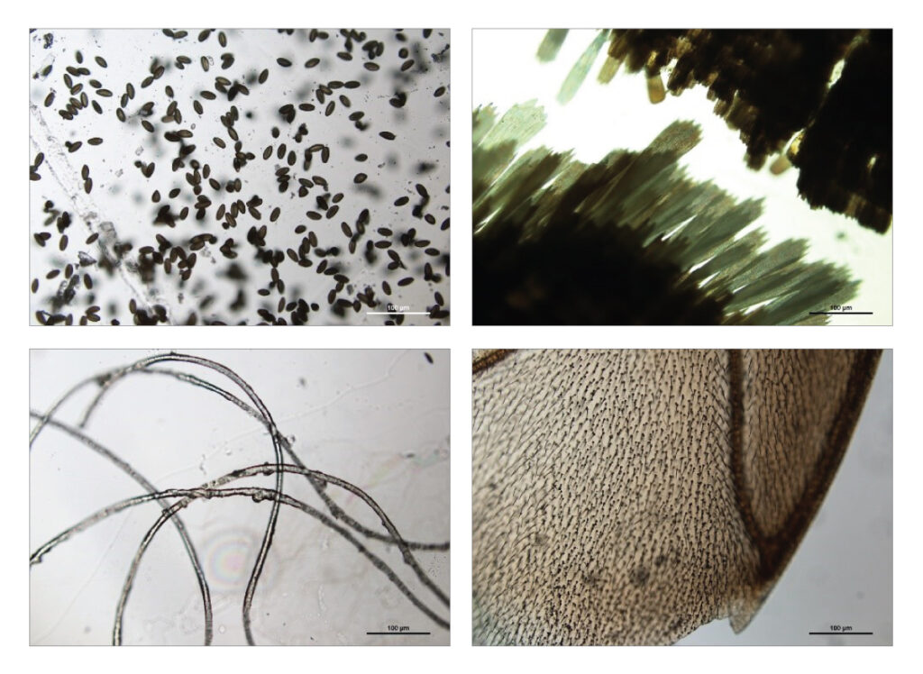
With the four main slider components made, it was time to choose our samples and begin assembling the preparations. Based on previous microscopical examinations of vintage microscope slider specimens, we chose samples typically used during that era: sugar maple pollen, moth wing and scales, wool, and a wing from a wasp.

Overall, we were happy with the quality of our wood slider preparations. The slight variation of the materials between each of the cells adds to the charm of these one-of-a-kind microscopical preparations.
So, why bother recreating an obsolete method of preparing specimens for the microscope? In doing this exercise, we have a better understanding and appreciation of how these microscopical sliders were made and can easily recognize these components when exploring the contents of an antique microscope’s wood box. This project has also raised more questions to explore in the future, and that’s always a good thing.

Comments
add comment