Microscope Activities, 15: Polarized Light
In the past, Hooke College of Applied Sciences offered a microscopy workshop for middle school and high school science teachers. We thought that these basic microscope techniques would be of interest not only for science teachers, but also for homeschoolers and amateur microscopists. The activities were originally designed for a Boreal/Motic monocular microscope, but the Discussion and Task sections are transferable to most microscopes. You may complete these 36 activities in consecutive order as presented in the original classroom workshop, or skip around to those you find interesting or helpful. We hope you will find these online microscope activities valuable.
EXPERIMENT 15: Converting the Microscope for Use with Polarized Light
Goal
To modify any biomedical or student microscope so as to convert it into a polarizing microscope.
Level
Basic
Materials Needed
- Polarizing film (~2”x 2”); empty 35 mm film container
- Plastic Petri dish cover (2-inch; 50 mm)
- Quick-setting (5-minute) epoxy
Optional:
- Additional polarizing film (two pieces 3” x 3”)
- Motic Polarization Kit
- Polarizing sunglasses
- 4” plastic 360º protractor
- Selection of water-soluble chemicals
- Procedure
Take the 2” x 2” polarizing film in hand, and look around you for a source of reflected light, such as a piece of glass, shiny furniture surface, waxed asphalt tile floor, etc. Try to position yourself so that the glare of the reflection is between you and the light source, as, for example, a glass plate or other reflecting surface between you and a window. Now, look at the reflection through the 2” x 2” polarizing film, and rotate the film either clockwise or counter-clockwise. As you do this, you will notice that at some point in rotation the reflection will disappear; then as you continue to rotate, the reflection will reappear, only to disappear once again as you continue to rotate the film. Stop rotating when you see the reflection disappear and notice the orientation of your polarizing film.
It is vital now that you know that the reflected light is coming at you with an East/West—that is, horizontal—vibration direction. Your film allows light to pass through it in only one direction—that’s why it’s called a linear polarizer; that one direction is often referred to as the privileged direction. When you rotate the film so that its privileged direction is parallel to the E/W reflected light, it will allow the reflected light to pass through, and you will continue to see the reflection. When you rotate the film so that its privileged direction is perpendicular to the E/W reflection, the film blocks the reflected light from passing through, and you see the reflection disappear.
You stopped rotating when the reflection disappeared, and you know the reflected light is vibrating E/W; therefore, your film’s vibration direction, or privileged direction, is N/S; i.e., up and down, or vertically, as you are holding it. Mark one edge of the film to indicate its vibration direction.
Next, cut a 15 mm wide strip off of either edge that is parallel to the film’s vibration direction, and mark the vibration direction on the 2” long 15 mm wide strip, using a bit of slide label. (Figure 15-1) illustrates two such strips, with their vibration direction marked with a line.
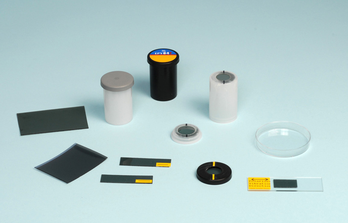
This 2” long strip is going to be your polarizer, which we are going to place in the light path below our specimen in such a way that it will allow our specimen to be illuminated with light vibrating only E/W (left/right; 3 o’clock/9 o’clock).
Next, select either the plastic container or the plastic cap of an empty 35 mm film canister, and drill, cut, or punch out a hole—about 1 cm, or so, in diameter. From the remaining piece of polarizing film, cut out a disc 1.5-2 cm in diameter. Using a 5-minute epoxy, cement this polarizing film disc over the hole in the bottom of the film canister, or cement the film into the underside of the plastic cap. Figure 15-1 illustrates three different examples—one is in the base of a translucent container, and two are in caps (one black, one translucent).
When the cement is dry, look through the film at a reflection, rotate the cap or canister, and mark the privileged vibration direction on the cap or canister. This component is called the “analyzer”, or, more specifically in this case, a “cap analyzer”; we will be placing this analyzer on top of the eyepiece.
Any scraps of polarizing film left over can be saved for other experiments, or you can cement a piece to a microscope slide, and label it, so as to make a permanent reference of known vibration direction; such a reference slide is illustrated in the lower right of Figure 15-1.
Now to convert our Boreal/Motic microscope into a polarizing microscope. Take your “polarizer” (15 mm wide strip of polarizing film with its vibration direction marked) and place it in the 15 mm wide groove machined into the top of the light exit port, as illustrated in (Figure 15-2).
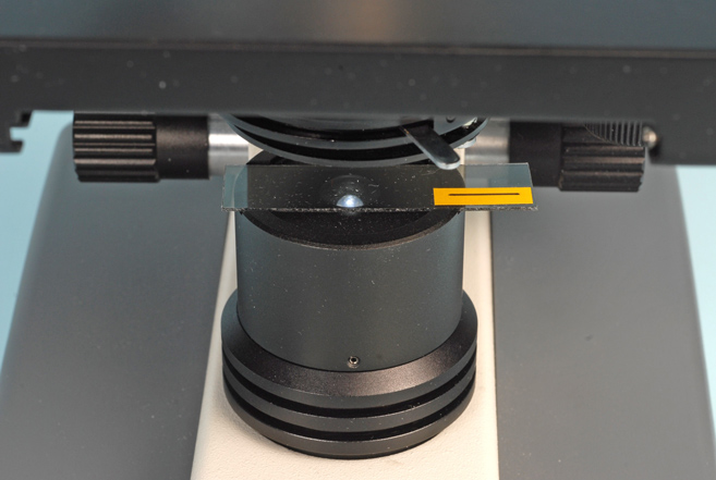
Your specimen will now all be illuminated with light vibrating E/W, which is the current DIN standard direction for polarizing microscopes. The polarizer only allows passage of about 32% or so of the light that enters it (the vector component of all other direction being blocked), so that you probably will need to adjust the rheostat for maximum light output, and you may need to swing out the lower ground glass, as you could lose 15% of your light from that component.
Next, place your analyzer right on top of the eyepiece—or invert the canister analyzer over the eyepiece, as illustrated in (Figure 15-3).
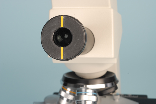
If the analyzer is rotated so that its vibration direction is N/S, as illustrated in Figure 15-3, you will have configured your microscope for what is called “crossed polarizers,” or, “crossed polars,” for short, and this will increase the analytical capability of your microscope many times. If you rotate the analyzer so that it is 10º-20º off of N/S, you will have the condition of slightly uncrossed polars. If you rotate the analyzer so that its vibration direction runs E/W—that is, the same as the polarizer—you will have the condition of parallel polarizers, or parallel polars.
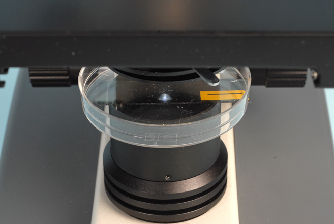
In a professional polarizing microscope you have slots cut into the bodytube for insertion of so-called “compensators”; these retard light by some specific amount, and are used for determining specific optical properties of crystalline materials that are useful in their identification. We can achieve similar visual effects by utilizing the cover of a 2” plastic Petri dish, placing it in the light path somewhere between the polarizer and analyzer. A convenient location for placing and manipulating our compensator is right on top of the polarizer, as illustrated in (Figure 15-4). Here it is easily and quickly inserted, removed, rotated, or moved about.
Finally, a proper polarizing microscope is equipped with a rotating, graduated stage. The Boreal/Motic microscope comes equipped with a non-rotatable square stage. We have several options to further modify our microscope. The simplest expedient is to remove the slide holder by loosening and removing the two thumb screws that fasten it to the stage. That way we will at least be able to rotate our specimen slide freehand.
A more elaborate modification may be introduced by making a sort of lazy Susan out of a 3½” diameter 360º plastic protractor, Figure 15-5, which can be mounted on a ball-bearing; a ½” – ¾” hole should be drilled through the center of the protractor.
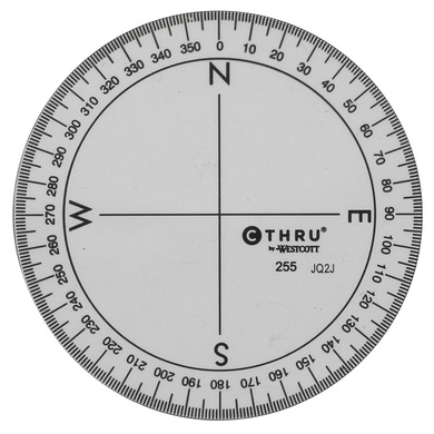
Another solution is to make a rotating stage out of a plastic 47 mm diameter membrane filter holder—the plastic lid can be lubricated to rotate in its base piece; again, a hole needs to be drilled through the combination.
Still another solution, if angular measurements are to be made, is to use an eyepiece with a full 360º protractor graticule.
To start with, however, it will be enough to just have crossed polarizers, our compensator, and freehand orientation of our specimen slide.
Discussion
Light does not necessarily travel at the same velocity through all transparent materials. Depending on the internal arrangement of the atoms and molecules, light can travel through transparent materials with one, two, or three characteristic velocities. The ratio of the velocity of light through a material relative to its velocity in a vacuum is known as the refractive index. Amorphous materials, such as gases, glasses, liquids, and unoriented polymers have just one characteristic refractive index; so do crystals that are in the isometric or cubic crystal system, such as common table salt. Crystals in the tetragonal and hexagonal crystal systems have two refractive indices, while crystals in the orthorhombic, monoclinic, and triclinic systems have three refractive indices.
Why are these facts important? Because it turns out that amorphous materials, and crystals in the isometric system cannot be seen between crossed polars; they are said to be “isotropic.” All other transparent things in the world will show up in some kind of color or variety of colors when viewed between crossed polars, and are said to be “anisotropic”. Thus, from an analytical viewpoint, merely looking at any sample at all orientations between crossed polars will allow you to say whether they have one, or more than one, refractive index.
In another experiment we will learn how to determine the specific refractive index values, and we are on the road to identifying unknowns, because everything has a specific value or set of values of refractive index.
When we set up the polarizer and analyzer for the crossed polars condition field, and look in the microscope with no specimen in place, we will not see anything. The field of view will be black, and will remain black if we look at gases, glasses, liquids, unoriented polymers, or isometric crystals. You may try this by looking at table salt on a glass slide; nothing will be seen between crossed polars.
On the other hand, recrystallized sugar or aspirin, for example, will show up in a variety of colors, because these materials have more than one refractive index; they are anisotropic.
The colors that one sees between crossed polars are not the colors in the rainbow, i.e., spectral colors; they are interference colors in the Newtonian series, and are the same colors seen in soap bubbles and on floating oil slicks following a rain, or between two microscope slides that stick to one another on removal from a box. The specific color seen depends on two things: the numerical difference between the principal refractive indices—known as the “birefringence”—and the thickness of the sample. The specific “retardation” value of the polarization color seen, the birefringence, and the thickness can be graphically related in a color chart, as was done about 130 years ago by Michel-Lévy.
If a sample consists of more than one component, and is a mixture of both isotropic and anisotropic materials, they are most quickly detected by using slightly uncrossed polars (under crossed polars the isotropic components would not be seen).
Compensators will modify all colors seen between crossed polars by adding or subtracting retardations to the colors seen without the compensator, all depending on the orientation of the samples.
Task
Prepare a polarizer and analyzer as described in the Procedure section, and install them on your microscope. Remove the slide holder. Using your 10X objective to start, look at a slide preparation of quartz, both with and without the cap analyzer in place. Compare the view of quartz between crossed polars, with and without your compensator (you may wish to leave the compensator in all of the time!).
Compare the appearance of the quartz sample with calcite. Rotate both slides and notice the change of appearance.
Look at some synthetic fibers, such as Orlon and nylon, and compare their appearances with some natural plant and animal fibers, such as cotton and wool and rabbit hair. Rotate the slides.
Next, place two separate drops of water on a microscope slide, and dissolve a few crystals of salt (sodium chloride) in one drop, and a few crystals of sugar (sucrose) in the other. Allow these drops to evaporate, so as to recrystallize the materials; do not use a coverglass. Compare these two crystalline materials between crossed polars, with and without your compensator. Recrystalize from water one or more of the following: cobalt chloride, copper sulfate, nickel nitrate, potassium dichromate.
Compare the appearance of potato starch and corn starch between crossed polars, with and without your compensator.
Teacher’s Note 1: Motic Polarization Kit
There is an optional Motic Polarization Kit available for purchase from the manufacturer’s dealers. This kit consists of two parts: a stage plate adapter which has a rotating, graduated stage (with slide spring clips), and built-in polarizer, and a cap analyzer (Figure 15-5).
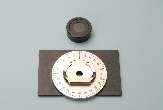
The stage plate with its rotating stage and built-in polarizer is placed on the microscope stage, and the analyzer is placed over the eyepiece.
It is true that you may wish to purchase their polarization kit, rather than make your own conversion. However, there are three important features of this kit that you should be aware of before making a decision:
- First of all, the polarizer, which is fixed and built into the kit at the factory, has its privileged vibration direction running N/S, which is contrary to DIN Standard.
- Secondly, notice that the graduations on the rotating stage read counterclockwise; this, too, is in the opposite direction to that dictated in the DIN Standard.
- Finally, notice the white line on the cap analyzer; you expect this to be indicative of the vibration direction of the analyzer; it is not; the vibration direction is actually E/W! Again, not only contrary to DIN Standard for the analyzer vibration direction, but perpendicular to the white line (the manual directs one to orient the white line on the cap analyzer parallel to the white line on the stage seen just above the “0” in the figure).
Teacher’s Note 2: Photography in polarized light using the built-in digital camera.
The conversion of the microscope for use with polarized light as described in this experiment is for visual use only. The built-in digital camera accepts projection of the image from the objective directly onto the chip of the built-camera; the eyepiece cap analyzer will not be in the light path to allow recording of the specimen between crossed polarizers. To photograph specimens in polarized light using the built-in camera, proceed as follows:
- Rotate the nosepiece to the objective desired for photography in polarized light.
- Mark the top front of the objective with a marking pen, making sure the mark is centered when viewed from the front.
- Unscrew the objective completely out of the nosepiece.
- Cut a piece of polarizing film into an 18 mm diameter circle.
- Determine the vibration direction in the disc of polarizing film, and place the disc on the back of the objective such that the vibration direction is in line with the mark from the marking pen.
- Carefully screw the objective back into the nosepiece.
You now have a fixed N/S analyzer in the rear of the objective, and you can monitor specimens between crossed polarizers on your laptop screen, instead of looking in the microscope’s eyepiece. If you do not have a completely black background, you may rotate the polarizer on the light exit port beneath the substage condenser slightly, one way or the other.
Additional Reading
The subject of polarized light microscopy is covered by a vast literature, and research-grade polarizing microscopes serve as the principal investigative instrument in industrial, forensic, and government laboratories, where quantitative results are imperative. However, for qualitative investigations, simple conversions of any microscope using a couple of pieces of polarizing film are adequate for years of observations. To learn more about polarized light in general, its history and applications, the following annotated bibliography is provided.
Polarized Light – An Annotated Bibliography
Anon. (1945) Polarized Light and its Application. Polaroid Corporation, Cambridge, Massachusetts, 46 p.
This booklet was prepared by the Polaroid Corporation to explain, in very basic terms, the principles of the nature and production of polarized light, including a number of common applications of polarized light, such as, sunglasses, lighting, photography, automobile headlight glare, stereo-optic photography, microscopy, strain analysis, etc.
Anon. (1963) Polarized Light. American Institute of Physics, New York, 103 p.
This paperback book consists of selected reprints of important papers on polarized light. It was a Project of the American Association of Physics Teachers Committee on Resource Letters. Try to get a copy of this booklet, as it contains all of the fundamental, historically important articles on the subject of polarized light. This booklet is a better choice for the teacher, than the more extensive and expensive Billings publication, q.v.
Anon. (1999) Polarization of Light. Leica Microsystems, Buffalo, New York, 46 p.
This publication may be obtained online from the Leica Microsystems, Inc. website. The basic theory and demonstrations presented are designed to provide background in the principles of polarized light, as applied to strain analysis, fibers, microscopy, plastics, etc. This is essentially Todd’s booklet written for Bausch & Lomb (see below); same text and bibliography; interestingly, Hartshorne’s name, which was misspelled “Marthshorne” in Todd’s booklet, has been carried over misspelled into this Leica publication. The publication is now a companion booklet to the Leica Tabletop Polarization Demonstrator.
Billings, Bruce H. ed. (1990) Selected Papers on Polarization. SPIE Milestone Series, Volume MS23 SPIE Optical Engineering Press, Bellingham, Washington, 719 p.
This book is a compilation of outstanding, historically important articles on polarized light selected from the world literature on the subject. Common to other books in the Milestone Series, the editors believe that there is no substitute for reading the original papers on any subject. The first article is that of Nicol, published in 1828, in which he describes the means of cutting, arranging, and cementing calcite crystals to produce the polarizing prisms that still bear his name today. The next four articles are by E.H. Land, in which he tells the story of how he invented sheet polarizers. Seven other articles deal with applications of polarizers. Section Two includes thirty-one articles on Polarization State Shifters; Section Three consists of seventeen articles on Mathematical Analysis and Measurement of Polarization States. Section Four contains twelve articles on Depolarizers. The last Section consists of 28 original articles on Polarization Filters. This is an advanced reference.
Henderson, Herbert S. (1979) Adapting a Simple Biological Microscope for use with Polarized Light. Microscopy 33 499-502.
This article describes rather advanced adaptations for converting a biological microscope into a polarizing microscope. Parts of other microscopical equipment and accessories are used, and fitted to the converted instrument, including a rotating stage made up from parts of a centering mount.
Jones, William G., Thorne, Peter S. and Clere, Jerry L. (1986) Low Cost Polarized Microscopy. Applied Industrial Hygiene. 4 (1) 191-195.
This article describes the conversion of a biological microscope into one suitable for the analysis of asbestos. Washers, wires, a Gelman Analyslide®, cyanoacrylate, a hacksaw blade, and polarizing film are utilized. The authors report that the cost was “a few dollars … and approximately one hour … labor”.
Kliger, David S., Lewis, J.W., and Randall, C.E. (1990) Polarized Light in Optics and Spectroscopy. Academic Press, New York, 304 p.
This is an advanced text, especially for spectroscopists utilizing polarized light; it involves Jones calculus, Mueller calculus, Jones matrices, Mueller matrices, and the Poincaré sphere.
Können, G.P. (1985) Polarized Light in Nature. Cambridge University Press, Cambridge, London, 172 p.
This is an attractive and highly informative book devoted to polarized light: what it is; how to observe it; where it occurs in nature; nocturnal sources; minerals in polarized light; formation of polarized light from unpolarized light; alteration of the state of polarization by reflection and other mechanisms.
Highly recommended.
Land, E.H. (1951) Some Aspects of the Development of Sheet Polarizers. Journal of the Optical Society of America 41 957-63.
This short, but very important article by Edwin Land reviews the 25 years of activity by the author and his co-workers in the development of synthetic sheet polarizers. The early 19th Century work is briefly described, and then Land describes the various stages of the modern development of synthetic sheet polarizers in his laboratory. This paper is reprinted in Billings (see above), and in the collection by the American Institute of Physics (Anon. above).
Pereira, Jonathan (1854) Lectures on Polarized Light. Longman, Brown, Green, and Longmans, London, 311 p.
This is the Second Edition of one of the earlier textbooks on polarized light, including one lecture devoted to the microscope. This excellent book may be difficult to find, due to its age, but will be essential for those interested in the early history of polarized light applied to the microscope. First Edition 1843.
Pye, David (2001) Polarized Light in Science and Nature. Institute of Physics Publishing, Bristol and Philadelphia, 124 p.
This paperback resulted from a demonstration lecture that Professor Pye gave as the Royal Institution Christmas Lecture in 1985. It is one of the most recent books to discuss the origin and nature of polarized light, its action through crystals, left-and right-handedness, scattering, reflection, circular polarization, and seeing polarization – accompanied by color plates. The discussions of circularly polarized light and the use of polarization for navigation by bees, and movement of Daphnia are particularly well done. Recommended.
Shurcliff, William A. (1962, 1966) Polarized Light; Production and Use. Harvard University Press, Cambridge, Massachusetts, 207 p.
This is a wonderful book on polarized light, but not a beginner’s text. The author acquired his early training in the research laboratory directed by Dr. E.H. Land. Another one of Land’s colleagues was Dr. R. Clark Jones, who invented the Jones calculus to explain polarization in multi-domain systems; Jones calculus is used in this book. This will be the text to consult when the reader is ready to utilize both Mueller and Jones calculus and matrices. Van Nostrand published a paperback version of this book for The Commission on College Physics in 1964 under the title Polarized Light.
Spottiswoode, William (1874) Polarization of Light. MacMillan, London, 129 p.
This is another of the older, classic texts on polarized light, along with the book by Pereira, which will be difficult to obtain, but which will be essential for anyone interested in the historical background of the application of polarized light to the microscope.
Swindell, William ed. (1975) Polarized Light. Halsted Press, Division of John Wiley, New York, 418 p.
This volume is the first in a series of Benchmark Papers in Optics. It is made up of facsimile reprints and/or excerpts of all of the classic, historical writings on polarized light, starting with early studies by Bartholinus, Huygens, Newton, Malus, Fresnel, Brewster, and Nicol; through Faraday, Stokes, Poincaré, and Wiener; to more modern treatments, including Jones Calculus throughout the 1940’s. There are also separate chapters on Other Descriptions of Polarization, and Synthetic Polarizers (Herapath, Land, and Land and West). The concluding chapter consists of two bibliographies on polarized light, including those from The Proceedings of the Optical Convention (1905), and from Shurcliff, q.v. above.
Todd, Hollis N. (1960, 1964, 1970) Polarization of Light; Basic Theory and Experiments. Bausch & Lomb, Rochester, New York, 53 p.
This little booklet was prepared to accompany the Bausch & Lomb Classroom Demonstrator and Advanced Demonstrator for polarization; the kit contained polarizing film and several anisotropic specimens.
West, C.D. (1942) Polarizing Accessories for Microscopes. Journal of Chemical Education. 19 66-70.
The author describes where to place polarizing film to act as polarizer and analyzer. The making of stepped compensators is described. Microscopes with rotating stages are recommended, but those with both rotating and fixed stages are illustrated and described.
Winchell, Horace, and Walton, Matt S. (1949) An Inexpensive Petrographic Microscope. American Mineralogist 34 688-691.
The authors describe the use of polarizing film to convert Bausch & Lomb and Spencer biological microscopes. Their rotating stage, however, was made by the Yale University machine shop.
Wood, Elizabeth A. (1964) Experiments with Crystals and Light. Bell System Science Experiment No. 4 – Bell Telephone Laboratories Inc. Later published by Van Nostrand, New York, 109 p.
This, and later versions, is one of the best starting places for the understanding of polarized light, especially as it applies to elucidating the optical characteristics of crystals. The book originally came supplied with polarizing film, and was part of an educational kit made available for educational purposes by Bell Telephone Laboratories. See next reference.
Wood, Elizabeth A. (1977) Crystals and Light; An Introduction to Optical Crystallography. Dover Publications, Inc., New York, 156 p.
This is a revised republication of Elizabeth Wood’s earlier book (see above). Van Nostrand published it first, and this is the Dover paperback reprint. A basic, highly-recommended book. Hint: put a couple of 2”x 2” pieces of polarizing film in a small coin envelope, and keep it in your copy.
Other Useful Books That Deal With Polarization
Minnaert, M. (1940, 1959) Light and Colour in the Open Air. G. Bell and Sons Ltd., London, 362 p.
Dover reprinted this book in paperback form in 1954.
Wood, Elizabeth A. (1968) Science for the Airplane Passenger. Houghton Mifflin, Boston, 227 p.
Dover published a revised paperback version of this book in 1975 under the title Science From Your Airplane Window.
Polarized Light and Biological Specimens
There are three books devoted exclusively to the application of polarized light methods to the observation and investigation of biological specimens – all three are old, and all are in the German language:
Schmidt, W.J. (1924) Anleitung zu polarisationsmikroskopischen Untersuchungen fϋr Biologen. Verlag von Friedrich Cohen, Bonn, Germany, 64 p.
Schmidt, W.J. (1924) Die Bausteine des Tierkörpers in polarisiertem Lichte. Verlag von Friedrich Cohen, Bonn, Germany, 528 p.
Valentin, G. (1861) Die Untersuchung der Pflanzen- und der Thiergewebe in polarisiertem Lichte. Verlag von Engelmann, Leipzig, Germany, 312 p.
Comments
add comment