Microscope Activities, 31: The Virtual Image
In the past, Hooke College of Applied Sciences offered a microscopy workshop for middle school and high school science teachers. We thought that these basic microscope techniques would be of interest not only for science teachers, but also for homeschoolers and amateur microscopists. The activities were originally designed for a Boreal/Motic monocular microscope, but the Discussion and Task sections are transferable to most microscopes. You may complete these 36 activities in consecutive order as presented in the original classroom workshop, or skip around to those you find interesting or helpful. We hope you will find these online microscope activities valuable.
EXPERIMENT 31: The Virtual Image
Goal
To understand the characteristics of the virtual image by producing one, plotting its location, and comparing it to the original object. Also, to understand the difference between a real image and a virtual image, and how these relate to the microscopical image.
Level
Basic
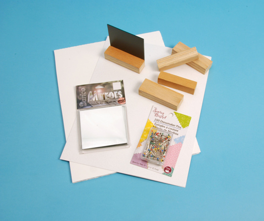
Materials Needed
Figure 31-1 illustrates the needed materials, including:
- A mirror. The one used here is 3” square; a package of five 3-inch square mirrors was bought at Hobby Lobby for $1.99
- Scrap wood cut to the width of the mirror, and glued to the back bottom of the mirror so that the mirror will stand up—see assembled mirror at the top of Figure 31-1
- Copier paper, or thicker stock, 8½” x 11”
- Foamboard, corkboard, or corrugated cardboard, 8½” x 11”—the figure shows a piece of paper and foamboard (Hobby Lobby, 20” x 30” x 3/16”, $1.00)
- Dressmaker Pins with colored plastic heads (Hobby Lobby, 200 Dressmaker Pins #17, 1-1/16”) in red, white, blue, green, yellow
- 12” rule
- Pen or pencil
Procedure
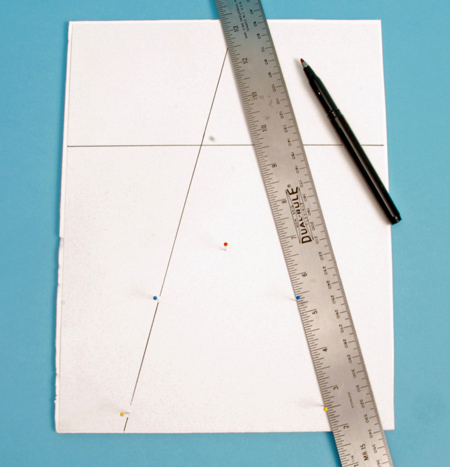
Draw a line all the way across the narrow side of a piece of 8½” x 11” paper, approximately 3½” from the top side, and place the paper on an 8½” x 11” piece of foamboard, corkboard, or corrugated cardboard.
Place the mirror, with its wood support, on the drawn line, being careful to line up the back side of the mirror on the line; i.e., the side with the silver reflecting surface.
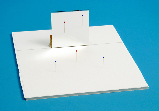
Select a colored dressmaker pin to act as the object, and stick it through the paper and into the support board about 3” in front of the mirror, and centered on it. In Figure 31-2, a red-headed pin has been chosen to be the object.
Take two additional dressmaker pins of a different color—blue in the figure—and stick them on either side of, and ~3” away from the object pin, so as to form an inverted “V” shape, as shown in Figure 31-2; the exact distances and placement do not matter. These two blue pins will be our front sights. The completed set-up up to this point is illustrated in Figure 31-2. It is now important to note that there is an image of the red object pin seen in the mirror; the image in the mirror is a virtual image; it appears to be not in the plane of the mirror, but somewhere behind the mirror. Our job is to determine precisely where and how far behind the mirror that virtual image is, and to consider some of its characteristics.
To do that, we proceed as follows:
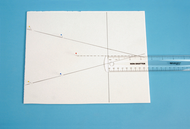
Select still another color dressmaker pin—here, yellow —that will act as a rear sight. Get down to eye level with your setup. Holding a yellow head pin near the front edge of your paper, sight through the yellow head of the pin you are holding; and line it up with the left-side blue head pin until both are exactly lined-up with the reflected image of the red object, as illustrated in Figure 31-3.
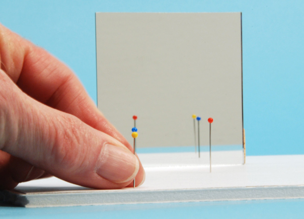
Repeat with a second yellow head pin through the right-side blue pin, lining them up with the reflection of the red object pin. When you are finished, the complete setup should look like Figure 31-4. The yellow and blue pins on both left and right sides are exactly lined up with the reflected, in-the-mirror- image of the red object pin.
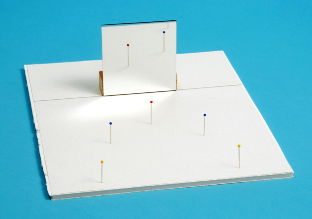
Remove the mirror, take your rule and pen, line up the rule along the blue and yellow pins, and draw a line extending to beyond where the mirror was (Figure 31-5). Do this on both sides. Where the lines cross behind the mirror is the precise location of the virtual image of the red object pin.
Measure the distance from the red object pin to the mirror line, and compare that distance to the distance between the mirror and the virtual image of the red object pin (Figure 31-6). The distances should be the same, or very close, within experimental error.
Discussion
The word “real” means not artificial, fraudulent, or illusory; occurring or existing in actuality; existing as a physical entity having objective independent existence. The word “virtual” means being such in essence or effect, not in reality; something where existence is inferred from indirect evidence. In optics, these terms are used to describe images—real image and virtual image; they can be distinguished by a simple test; namely projection; whether they are capable of being displayed on a screen. For example, when you go to a movie theater you see on the screen a real image of the actors and the scene conveyed to the screen by the projection lens through the action of a powerful light passing through moving film. There is nothing seen between the projection lens and the screen, because there is no screen there, but if you hold a piece of paper up anywhere in the light beam between the lens and the screen you will see the images projected on the paper (of course the images will be out of focus, unless the projection lens is readjusted for the new “screen” at the closer distance). If an image can be projected onto a screen, or piece of paper, it is a real image.
In the experiment that you just performed here, you distinctly saw the image of the red object pin when you looked in the mirror; that image does not lie in the plane of the mirror, but at a distance behind the mirror that is equal to the distance that the object is in front of the mirror. If you now place a piece of paper or screen behind the mirror exactly where the image of the object pin seems to be, you will NOT see its projected image; you will not see anything there, because it is a virtual image. A virtual image is one formed from points which divergent light rays seems to emanate, without actually doing so. Also, the mirror image has its parts arranged reversed relative to the object.
What does all this have to do with a microscope? When you use a microscope in the normal manner, and look down into the eyepiece, you see an enlarged image of your specimen. But where exactly is that image? Is it inside of the eyepiece? No, it’s farther away. Hold a piece of paper where the image appears to be; do you see it projected on the paper? No. The enlarged microscopical image that you see when you look down a microscope is a virtual image that lies about 10 inches (250 mm; standard viewing distance) away from the eyepoint (see Experiment #6). The microscopical image is, in reality, not where it appears to be; it exists as a consequence of a change in the angular dimension of the real image on your retina. Light rays exiting the eyepiece are parallel, and, therefore, focused at infinity, when we are looking into the microscope in the normal manner.
If we now move our head out of the way, and hold a piece of paper anywhere over the eyepiece, but above the eyepoint, we will see our specimen projected on the paper, but it will be out of focus (the light rays are focused at infinity….remember?); this projectable image is a real image. We may adjust the focus knobs to get a sharp image of the specimen on the piece of paper, in which case we have now converted the microscope from a visual instrument to a projection instrument or microprojector; this is the principle of the photomicrographic camera.
If you hold a pocket magnifier up to your eye, and then bring an object close to the front focal plane, you will see an enlarged image of the object; the enlarged image that you see using a pocket magnifier is a virtual image; you cannot demonstrate the enlargement by projecting it on a piece of paper. You can, however, not look through the pocket magnifier, but just hold it about one focal length away from a piece of paper, and see an inverted image of distant windows; used in this way, the inverted image of the windows is a real image, because it is projectable.
Task
Produce both virtual and real images using a pocket magnifier. Demonstrate a real image using a compound microscope, and the next time you are looking into your microscope, concentrate on the enlarged image that you see, and ask yourself where, exactly, is it located, and then try projecting it.
Comments
add comment