Polarized Light Microscopy in the Conservation of Painting
Editors’ note: Marigene H. Butler (Mrs. Daniel K. Butler) wrote this article in the late 1960s for what was supposed to be a centennial volume in commemoration of receipt of its state charter in 1869 by the State Microscopical Society of Illinois (SMSI). The planned 100th anniversary volume was never published because of a set of unfortunate circumstances. In 1970, two of the contributors to the volume arranged to have a limited number of preprints of their articles issued—Marigene Butler’s was one of these. Recently, while counseling one of the 3+1 students at Hooke College of Applied Sciences who elected to specialize in pigment identification and painting conservation, this article was resurrected. The editors, on rereading this 45-year-old article, realized that it is a succinct and lucid document describing the basics of polarized light microscopy as applied to conservation of painting, and is just as useful today to students beginning their careers in painting conservation as it was 45 years ago, and they have, therefore, decided to reprint it here.
At the time of the writing of this article, Marigene H. Butler was Associate Conservator at the Art Institute of Chicago. She left there in 1973 to become Director, Intermuseum Laboratory, Oberlin, Ohio, providing conservation services to the seventeen Midwestern museums of the Intermuseum Conservation Association. In 1978, she became Head of Conservation at the Philadelphia Museum of Art, where she was responsible for planning and implementing conservation care and treatment for the entire museum collection, with a special expertise in the treatment of paintings; she retired from there in 1997.
Over the years, Mrs. Butler has provided pigment identification, percentage composition, and particle size distribution in appendices to the catalogs of major art exhibits, thus providing templates containing the technical details of pigment identification in addition to the non-scientific information normally supplied by art historians. The editors would like to thank Marigene H. Butler for her kind permission to reprint this article.
A polarizing microscope is an extremely useful tool in the conservation of paintings. For the conservator treating paintings, questions such as the following can be answered quickly, conclusively and without causing visible damage to the painting’s surface:
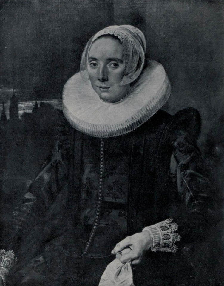
- Does the normal raw umber tone of this Frans Hals’ background extend under a possible later addition of a cityscape?
- Do the discolored patches in an area of copper resinate green in a late Flemish de Coter represent overpaint, or are they an integral part of the original paint layer whose surface has been chemically stained at some time?
The intimate view of the structure and materials of a painting which a polarizing microscope provides can corroborate the conservator’s theories about a specific problem in a particular painting. Polarized light microscopy can also point one’s thinking in a new direction, based on more accurate knowledge than unaided eyes or examination with a stereomicroscope can provide.
The Polarizing Microscope
The polarizing microscope is especially useful in the study of materials of paintings because with it one can readily identify crystalline materials, which include the majority of pigments. Also, most pigments can be distinquished immediately from the media; this aids identification of pigments. It also simplifies interpretation of the structure of a painting and measurement of the thickness and uniformity of each layer.
The unique characteristic of the polarizing microscope is the presence of two polarizing elements: the polarizer, located below the specimen, and the analyzer, located above the specimen. Light waves from the microscope lamp vibrate in numerous planes as they approach the polarizer. The polarizer passes only those light waves which vibrate parallel to the privileged (light passing) direction of the polarizer. Therefore, light which has passed through the polarizer vibrates only in parallel planes. Light rays from the polarizer will pass through the analyzer if the privileged direction of the analyzer is oriented in the same direction as that of the polarizer (1).
Looking through the microscope with no sample in view, the background will be bright when the privileged directions of the polarizer and analyzer are parallel. If either the polarizer or the analyzer is rotated, the background will gradually become darker. When the privileged directions of the polarizer and analyzer are positioned at 90° to each other (crossed polars), the background is black.
With crossed polars, isotropic materials (those having a single refractive index) such as glass, resins, and ultramarine, will not be visible. Anisotropic materials (those having more than one refractive index) such as azurite, basic lead carbonate, and cinnabar, will appear bright and characteristically colored against the black background. These colors are not the usual pigment colors (absorption colors), but are polarization colors and are related to the refractive indices and thickness of sample of the particular material being viewed.
A convenient way to view isotropic and anisotropic materials simultaneously is to cross the polars 75° instead of 90° (2). The background will be a medium gray, and isotropic particles, as well as anisotropic particles, will be visible. Isotropic particles such as media will appear about the same color and intensity as the background. Isotropic pigments will also be the same intensity as the background and will show their usual absorption colors. Anisotropic particles will appear much brighter than the background, showing their polarization colors.
Removing Samples from a Painting
These optical means of investigating the materials of a painting can be applied by viewing minute samples of the painting under the polarizing microscope. One can thoroughly study an area in question by means of two mounted samples:
- A sectional fragment, which can be made as small as 20 to 25 µm wide, containing all layers of the painting through to the ground.
- A particle approximately 50 x 50 µm to be crushed for identifying individual pigments (0.001 inch – 25 µm).
The smaller a sample is, the more informative it is likely to be, so long as it contains all materials present in the particular area. This is because the thinner and more transparent the sectional fragment is, the more transmitted light can pass through it under the microscope. Similarly, the smaller the particle is to be crushed, the more easily the pigment crystals and media within it can be dispersed so that each crystal is separate, allowing maximum light to pass through it for greatest visibility of its entire structure.
Samples are taken from a painting while viewing the area through a stereomicroscope at a magnification of about 10X – 15X. If the area of paint to be sampled is brushed with five percent polyvinyl acetate in toluene (having tested a fragment for non-solubility in toluene), a narrower section can be taken and the fragment is more likely to remain intact, particularly if egg tempera. The point of a 50 x 500 µm scalpel blade (#15) can be used to cut slowly down through the layers to be sampled, often at the edge of a loss or along a line of crackle. The fragment is loosened at the bottom with a fine-tipped tungsten needle, approximately 20 µm in diameter at its tip (such a needle can be made by heating a 1″ piece of tungsten wire red hot, stroking it over sodium nitrite, reheating and restroking until a fine point is formed (3)). Sometimes an adequately informative sectional sample can be taken with the needle alone, especially at the edge of a crack. The needle is similarly used to remove the second particle which will be crushed.
Once the samples are freed from the painting, they can be transferred with the needle to a glass microscope slide and viewed through the polarizing microscope at about 100X to determine if they are adequate enough to give complete information on the area being examined. For example, does the sectional fragment contain layers intact from ground through surface coating or uppermost layer of paint?
Mounting the Sectional Fragment
The sectional fragment is mounted in a drop of Aroclor® 1260 (4), a thermoplastic, chlorinated polyphenol compound with refractive index of 1.645. This particular Aroclor is colorless and transparent and remains highly viscous at room temperature. In practice, the drop of Aroclor 1260 is placed on a slide, using a glass rod. Under stereo magnification, the tungsten needle is used to lay the fragment of the painting upon the Aroclor. If possible the fragment is positioned on its side so all layers are readily visible. A No. 1-1/2 coverglass is laid over the fragment and gently pressed down upon the Aroclor to barely touch it on all sides of the sample. If the sample is allowed to sit undisturbed for 10 minutes or so, the coverglass will settle down onto the Aroclor and sample. Any bubbles present will tend to move away from the area of the sample. The sample is then ready to be studied under the polarizing microscope at magnifications ranging from about 50X – 250X. Because Aroclor 1260 does not solidify at room temperature, such mounts must be stored horizontally or may be ringed.
Examining the Sectional Fragment
When the mounted sectional fragment is viewed through the polarizing microscope, it can be “rolled” into any position by pushing on the edge of a round coverglass with a needle or a scalpel, moving the coverglass in a horizontal plane. The top, bottom, or edge of the fragment can be brought into the best view. The edge will, of course, reveal the complete sequence of layers. One can distinguish and study these layers from the ground, through layers of paint laid one over another, to any remaining surface coating.
Thickness of layers can be measured by using a calibrated ocular micrometer, making sure that the minimum dimension of a layer at a particular point is visible before measuring. Note can be made of special characteristics of materials in each layer such as particle size and color of pigments, the color of the medium, and the relative proportion of pigment particles to medium. Even if the cut edge is slightly uneven, ample information can be read from the fragment by focusing up and down on the sample and by rolling it and viewing it from different angles. This technique makes it completely unnecessary to remove, embed in a solid mount, and polish large cross-sectioned pieces of a painting.
One can also often observe whether one layer was applied over another when the latter was wet or dry. For example, in The Art Institute of Chicago’s (AIC) Rebecca Welcomed by Abraham, attributed to Barent Fabritious, in the area of the sunrise sky where a pale pink tone was brushed over a pale blue, one can see a few particles of blue pigment within the edge of the pink layer and vice versa, where the layers adjoin one another.
With fragments and rolling techniques, one area of a painting can be compared with another and similarities and dissimilarities of technique and materials noted. This was useful in the AIC Frans Hals painting Portrait of a Lady where the crimson lake and raw umber layers of the right background were also found under the cityscape in the several areas examined in the left background. This information was helpful in determining that the cityscape was a later addition, as had been suspected.
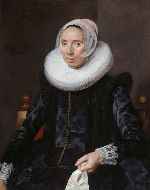
Even more helpful in the Hals painting was a pair of sections, one from the visible right hand knob of the sitter’s chair and the second from an area of the cityscape on the left, where it was suspected that the missing left knob of the chair might be. No left chair knob was visible in x-rays or in infrared and ultraviolet photographs, however a possible chair post was vaguely indicated in the x-rays. The section from the left area confirmed the presence of a chair knob. In it one found the same golden brown pigment as was visible in the right knob, exactly where one would expect to find it. It was over the crimson lake and raw umber background layers and under the overpaint pigments of the cityscape. This gave the conservator a sound basis of knowledge for proceeding to remove the later cityscape, ultimately revealing an inscription which dated the painting in 1627 and gave the sitter’s age (Figures 1 and 2; the inscription is not visible in this image).
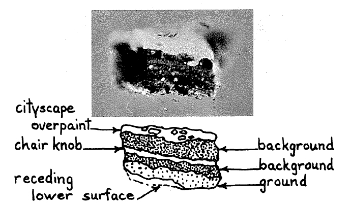
An additional sectional fragment, taken from 1/4″ to the right of the chair knob indicated that the artist had changed his mind and reduced the size of the knob after painting it. In this section one found the crimson lake and umber background layers, followed by golden chair tone, and on top of this, another pair of crimson lake and umber layers. Uppermost were azurite, yellow, and black of the cityscape layer. The upper background layers were of identical composition, particle size, color, and proportion of pigments to medium as the lower pair of background layers. The uppermost umber layer was, however, somewhat thicker than the lower umber layer (Figure 3).
(click to enlarge images)
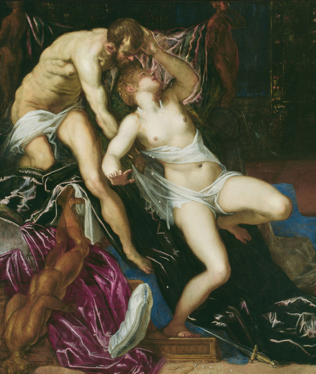
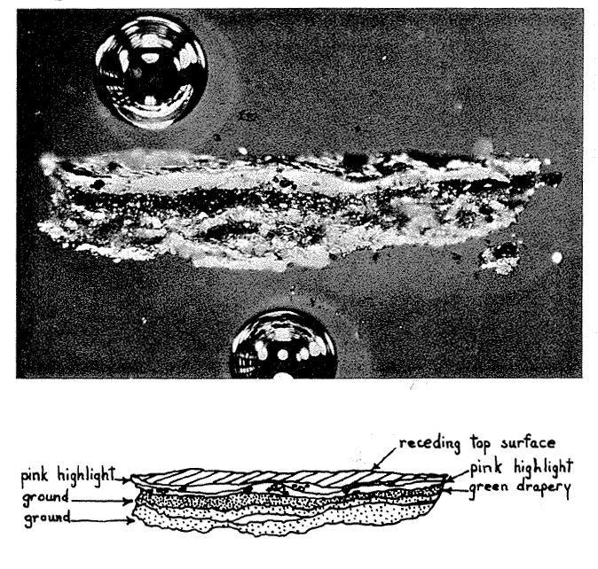
Another pair of sectional fragments mounted in Aroclor 1260 helped to explain why two areas of the same green drapery looked so different. Not only was the handling of the paint different in the two areas, but, as revealed by the sections, the materials used differed considerably. This occured in the AIC painting Tarquin and Lucretia, thought to have been done in the workshop of Jacopo Tintoretto about 1560 (Figure 4). Both areas of the green drapery were modeled with highlights of varying tones of pink. The pink hue in the top center region had a warm orange-red cast and extended over a broader area than in the bottom right corner where the pink had a dark crimson cast and was confined to a smaller area.
Upon examining the sectional fragments, that from the top center area revealed the following structural layers: two layers of an off-white ground; a layer of azurite, which with yellowed medium provided the dark green appearance of the drapery; a layer of grayish tone consisting of white colored with large flakes of crimson lake ranging from 3 – 40 µm and black particles ranging from 8 – 12 µm in diameter; and uppermost, a layer of white colored with smaller flakes of a crimson lake ranging from 1 – 24 µm in diameter (Figure 5).
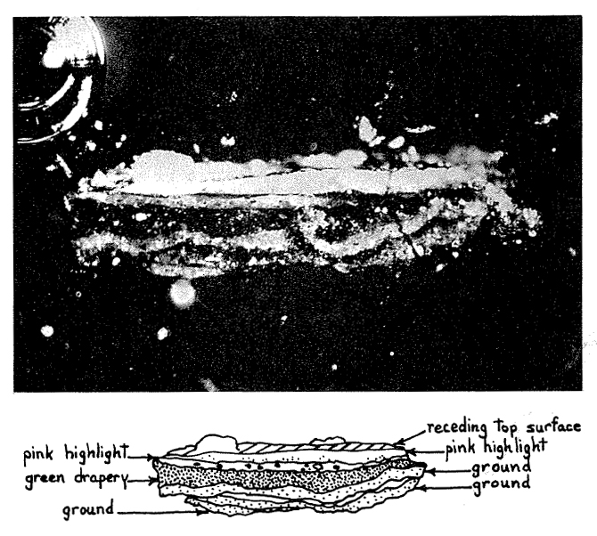
The second sectional fragment from the bottom right corner contained the same layers of ground and green as the first, followed by a pink layer colored with small particles of crimson lake, ranging from 4 – 10 µm, and only a few, very small 3 µm black particles. Uppermost, the lightest highlight was very similar in color to the layer beneath it, this time white colored with very small 1 – 3 µm particles of the same crimson lake. This layer was separated from the lower pink layer by a yellowish transparent material visible in uneven pockets between the two layers (Figure 6).
The crimson lake flakes in the lower layer of pink highlight at the top center appeared to be a darker lake in situ than those of any of the other three pink layers. However, when a crushing of this layer was compared with crushings of the other three layers, all four crimson lakes appeared to be identical in color. One concluded that the presence of black particles in this lower layer lessened the amount of light refracted through the layer by the white pigment, causing the crimson lake to appear darker. The combination of different particle sizes of crimson lake flakes and differing quantities of black pigment used in each of the layers produced the considerably different visual effects in the two areas of green drapery.
The question of whether overpaint was present on the surface of a discolored copper resinate green area in the AIC painting Madonna and Child with Angels by Colijn de Coter, mentioned earlier, was quickly answered midway through the cleaning process. By taking a sectional sample in an area where the surface of the green was discolored and studying it under the polarizing microscope, one could see that there was only one unified layer of green present. Therefore, it was concluded that the discolored area must be a surface stain, caused perhaps by the action of light or by chemical treatment at some time in the past. Had the stained area appeared in the sectional sample to be a separate layer, one might have concluded that it was old overpaint which could be removed from the original paint.
The knowledge gained from examining sections of a painting microscopically provides unforseen dividends in carrying out treatment. For instance, in our experience, the tones of inpainting can be matched to those of the original paint much more rapidly and accurately when one knows exactly the materials present and the layers in which they were used in a particular area. An example are the red robes of the Madonna in the de Coter. The under robe of the Madonna was found to receive its bluish-red tone from a crimson lake. The more orange-red outer robe consisted of cinnabar in its lighter areas, while its shadows were cinnabar glazed over with a crimson lake. lnpainting tones could therefore be adjusted toward the orange or blue depending upon their location.
The polarizing microscope can also act as a monitoring device during treatment. For example, when removing an old, tough, insoluble surface coating with a scalpel (#15 blade), one can check one’s scrapings under the microscope from time to time and ascertain whether any particles of the paint layer are being removed with the surface coating. The same check can be made when removing overpaint from original paint with a scalpel. At about 100X – 250X, using polars crossed 75°, with or without top light, a great deal of information can be learned which can contradict conclusions reached while working under a stereomicroscope at low power.
Lighting Conditions for Viewing Sectional Fragments
The arrangement of lighting used in viewing sectional fragments is extremely important for maximum visibility and correct interpretation of materials in individual layers of the fragment. In addition to transmitted light, set up for Köhler illumination, a pair of illuminators is used to light the specimen from the top to give reflected light. These separate illuminators are focused at a 20° – 45° angle upon the sample from approximately either side of the stage. Because of their oblique angle, there is very little reflection from the coverglass, which is sometimes a problem with vertical illumination.
The reflected light illuminates the top and sides of the sample and helps one to distinguish each layer of a sectional fragment, parts of which may be nearly opaque in transmitted light. The transmitted polarized light illuminates individual particles within the layers of the sample, rendering their colors and shapes more visible and therefore the structure of layers more discernible than would unpolarized light. Varying combinations of reflected light and transmitted light with either crossed polars (90°) or slightly uncrossed polars (75°) have been used. For maximum visibility of the layered structure of a sectional fragment, one uses reflected light together with transmitted light with fully crossed polars. This is the most effective way of illuminating the top and interior of a section and the dark field aids visibility. For maximum visibility of materials, one uses reflected light and transmitted light with slightly uncrossed polars, revealing both isotropic and anisotropic materials.
Mounting the Sample To Be Crushed
More specific identification of materials can be made with a crushed particle of the area already studied via a sectional fragment. This particle is mounted in Aroclor 5442 (4), a more viscous and permanent resin than 1260. At about 138°C, Aroclor 5442 is a thin liquid; when cooled to room temperature it forms a reasonably solid permanent mount.
This second particle is usually taken from a single layer of paint with the point of the scalpel. It is laid on a slide; covered with a No. 1-1/2 coverglass and crushed by pressing on the coverglass with a pencil eraser and moving the glass with a rotating motion to promote dispersion of the particle, separating pigment crystals from the medium. The slide is then placed on a micro hot plate and warmed slightly. A drop of warmed Aroclor 5442 is placed at the edge of the coverglass with a glass rod and allowed to run in by capillary action.
When the area under the coverglass is completely filled with Aroclor, the particles are again dispersed by pressing on the coverglass with a pencil eraser. This also aids in removing any air bubbles trapped around the particles. The slide can then be removed from the hot plate and placed directly on the microscope stage for examination. The Aroclor 5442 will cool and solidify within 30 seconds, giving a permanent mount. However, the slide can be warmed and the sample’s position adjusted at any time.
Aroclor 5442 is not only a simple mounting medium to use, but it also has a relatively high refractive index of 1.66 which makes it useful for the materials encountered in paintings. The greater the difference between the refractive index of the particle and that of the mounting medium, the more visible the mounted particle will be, due to increased contrast of the particle boundary (5). Particles of paint media mounted in Aroclor will have enough contrast around their boundaries to be readily visible. The more commonly used mounting media such as Canada balsam have refractive indices of about 1.53, so close to those of paint media that particles of paint media mounted in them are nearly invisible (at times these mounting materials may be desirable to show up colorless particles of non-media by making the paint medium invisible).
The majority of pigments have refractive indices in the range of 1.50 to 3.14. Aroclor’s 1.66 refractive index divides those of the lower refractive index pigments so that the Becke line test 6 can be used more informatively to determine whether the refractive indices of these pigments are higher or lower than 1.66 than it could with Canada balsam or other low refractive index mounting media in the 1.53 range (7).
Some pigment particles of very high refractive index reflect and refract so much light, even when mounted in a fairly high refractive index medium such as Aroclor 5442, that the particles appear quite opaque, especially when they are very small. Under such circumstances, the use of oblique top light in viewing the crushed sample greatly increases the visibility of the particles (8).
Identifying Pigments
Crushing the sample spreads apart the particles and medium so that one can view the entire structure of each individual pigment particle. The sample is studied under the polarizing microscope at a range of magnifications from about 100X to 1000X. This is done with slightly uncrossed polars (75°) for simultaneous visibility of isotropic and anisotropic materials present. The diameters of individual particles of the different pigments present can be measured with the ocular micrometer and the range of size noted for each pigment present.
Pigment particles can be identified in several different ways under the polarizing microscope. The simplest means is through visual comparison of their color, crystal shape and range of size, refractive index, and polarization colors with those of known samples mounted as reference Standard slides. Particles of the sample should be compared with those of a similar size in the reference standard slide at a particular magnification.
Relative refractive index of a specific particle can be checked, ascertaining whether it is higher or lower than that of the mounting medium, using the Becke line test. More precise refractive index can be determined by removing a particular crystal and immersing it in different liquids of known refractive index until a match is found. In practice, and with some experience, pigments can usually be identified without a specific determination of refractive index. A useful adjunct to the identification of pigments are Gettens and Stout’s tables of “Physical Properties of Pigments” (9).
Using crossed polars, one can observe whether a material is isotropic or anisotropic as only the anisotropic particles will be visible against a dark background. Polarization colors of an anisotropic crystal can be observed at some point as the stage is rotated.
Polarized light is especially useful in making very small anisotropic particles more visible, enabling them to be identified more readily. An example of this was found in examining the ground of the above mentioned Frans Hals painting. Under the stereomicroscope the ground was a uniform pale pink in color but one could not ascertain the cause of the pink tone. Only when a crushing of the ground was studied at approximately 300X with polarized light could one see that the coloring matter consisted of minute red particles, predominantly 0.5–3 µm in diameter, mixed with basic lead carbonate. Further study of the particles at 500X to 1000X and comparison with reference standard slides lead to their identification as hematite which was later corroborated by the electron microprobe.
In comparison with more elaborate equipment used for identification of materials, such as spectroscopy, polarized light microscopy proves to be more specific in information produced and to use smaller samples, as well as being more readily accessible within the conservation laboratory. For example, one frequently finds in early Italian and Flemish painting that only a few particles of a pigment are used to tint, often strongly, a particular tone. In the AIC Correggio Madonna and Child with Saint John and in the de Cater, a few particles of cinnabar are the sole coloring material in basic lead carbonate for the flesh tones. These few particles would comprise too small a part of the whole sample to be identifiable by more elaborate equipment such as x-ray diffraction. However, with the light microscope one can identify immediately what the effective coloring material is.
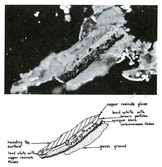
Similarly, more elaborate equipment would not indicate the structural order in which materials identified were found. With the microscope the structure of the sample is clearly indicated. A graphic example of this is Figure 7 where a sectional fragment of a shadow tone of a green leaf from the Correggio Madonna and Child with St. John is found to have the following structure: gesso at the bottom, followed by opaque black carbonaceous flakes, then a layer of basic lead carbonate with translucent and opaque browns, another layer of basic lead carbonate—this time with copper resinate flakes, and at the top, a copper resinate glaze (10).
Selecting a Polarizing Microscope
The type of polarizing microscope used is critical to the success of this entire approach. Due to the very small size of pigment particles and the importance of accurate color rendition, a highly corrected optical system and a strong light source are needed. Well suited to this purpose are the 100X, 40X and 25X Zeiss planapochromatic objectives in which chromatic aberrations are corrected for three colors and spherical aberrations for two colors as well as a correction for flat field. In addition to these one can use Leitz 10X and 4X planfluorite objectives which have chromatic and spherical aberrations corrected for two colors as well as a flat field correction. These planfluorites have a relatively long working distance which makes them useful for particle handling and for photomicrography, using top lighting in combination with polarized light.

Conclusion
Conservators and microscopists have several characteristics in common. Both are unusually perceptive in looking at things and in interpreting what they see. Both are highly dexterous. We have found it not too difficult for conservators engaged in the treatment of paintings to learn the basic elements of microscopy and to develop the skills needed for sampling paintings and interpreting those samples on the basis of their knowledge of the materials and techniques of painting.
The opportunity remains for more work to be done in further refining these techniques for examining the materials and structure of paintings with a polarizing microscope. For example, more precise sampling tools need to be developed, enabling smaller samples to be taken which would still be complete enough to provide adequate information to the conservator.
Techniques can be developed to use the polarizing microscope in other areas of conservation, for example, in studying the structure and behavior of the materials of historic textiles before treatment is undertaken. Much can be learned from observing a single dyed, soiled animal hair or cotton fiber as it reacts to different solvents. The combination of polarized light, high magnification, and minute samples can tell the conservator a great deal about any type of work of art, extending their knowledge of a specific object far beyond theories derived from observation with their eyes alone. This allows them to make decisions about treatment based on a more thorough understanding of the materials they are dealing with.
Acknowledgement
The author wishes to acknowledge Mr. Alfred Jakstas, Conservator, for suggesting and promoting the use of the polarizing microscope in the conservation laboratory of The Art Institute of Chicago; Dr. John Maxon, Associate Director of the Art Institute, for supporting the microscopy program; and John Gustav Delly of McCrone Associates, Inc. for advice and encouragement in furthering the use of the polarizing microscope in conservation of works of art and for their constructive criticism of this paper.
References
- Chamot, E. M., and Mason, C. W. Handbook of Chemical Microscopy. Vol. 1, 3rd Ed . (1958). Chapter 10.
- Dr. Walter C. McCrone, Walter C. McCrone Associates, Inc., a former student of C. W. Mason at Cornell University, was first to make extensive use of slightly uncrossed polars (75°) in polarized light microscopy.
- McCrone , W. C., Draftz, R. G., and Delly, J. G. The Particle Atlas. Ann Arbor Science Publishers, Inc., Ann Arbor, Michigan, 1967, p. 40.
Editor’s Note: This one-volume edition was soon followed with a six-volume edition, and is currently available free of charge at www.mccroneatlas.com. - Aroclor is a registered trademark of the Monsanto Chemical Company. Aroclor was available through 1977 from the Monsanto Chemical Company. Dr. Walter C. McCrone pioneered the use of the Aroclors as particle mounting media in 1939.
Editors’ Note: In the case of Aroclor 5442, contemporary microscopists may substitute Cargille’s Meltmount 1.662. - Delly, J. G. Mounting Media for Particle ldentification. The Particle Analyst 1, (8), 61-67, (April 20, 1968).
- Bloss, F. D. An Introduction to the Methods of Optical Crystallography. Holt, Rinehart, and Winston, New York, 1961, Chapter 5.
- Allen, R. M. Practical Refractometry by Means of the Microscope. 2nd Ed., R. P. Cargille Laboratories, Inc., 33 Village Park Road, Cedar Grove, New Jersey 07009, 1962 .
- McCrone, W. C. Top Lighting. The Particle Analyst 1, (9), 69-80 (May 5, 1968).
- Gettens, R. J., and Stout, G. L. Painting Materials, A Short Encyclopaedia. Dover Publications, Inc., New York, 1966, pp. 147-148d.
- Microanalyses of Pigments and Media from Correggio’s Madonna and Child With St. John, prepared for The Art Institute of Chicago by Walter C. McCrone Associates, Inc., 1968.
- Delly, J. G. How to Buy a Compound Microscope. American Laboratory, (April 1969).
- Agfa-Gevaert, Inc.
Read the next article by Marigene H. Butler.
Comments
Will Randle
Thanks for sharing this. Awesome.
add comment