A “Poor” Microscopist’s Inverted or Chemical Microscope
From time to time, it happens that minute objects inside a bottle or dish containing a liquid have to be observed and photographed in situ as sediment, without removing these objects from the inside of the jar before inspection. Typical examples are ampoules and bottles with parenteral solutions in pharmaceutical manufacturing in cases when contaminating particulate material is present. In such instances, inverted microscopes do a good job of observing these particles through the transparent bottoms of the containers, provided that the demands for picture quality are not too high. Inverted microscopes of this type have also been called “chemical microscopes” for more than a century-and-a-half, as they were extensively used for inspecting precipitated crystals and the like in wet chemical testing and crystallization experiments.
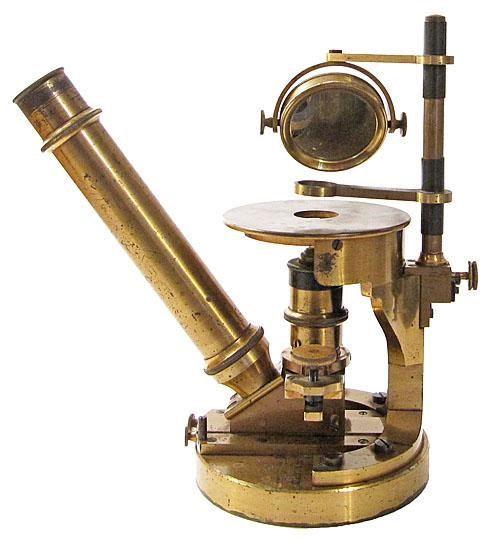
The classical design of this type of microscope uses a large stage on top of a rigid foot made of cast iron or machined brass able to support large objects, for example, cell culture bottles. A top-down lighting system with or without condenser optics is mounted above the specimen, held in place with a craning-out arm, while all of the other microscope optics are situated underneath the stage facing upwards, as for instance different objectives attached to a rotating nosepiece, a prism system to divert the light path upward, and a monocular or binocular head with eyepieces for visual inspection. More elaborate systems also have photographic camera attachments and additional contrasting techniques conveniently included. A typical example of a historical chemical microscope is pictured in Figure 1.
It is the purpose of this little communication to describe a simple, improvised setup for such an inverted or chemical microscope, with the limited financial means that a hobbyist can typically spend. I call the result the “poor” microscopist’s inverted microscope. Its application is needed only occasionally in the home laboratory of the author, so it is essential that the instrument be easily assembled and disassembled within minutes. The time-consuming step is proper optical alignment of all components. With some practice, this can be done within 15 minutes or so.
The primary components of this design are:
- An inspection shop microscope as used in, for example, metallographic field inspections
- An ocular-replacing digital microscope camera, with image processing software installed on attached notebook computer
- A rugged chemical laboratory ring stand, together with several clamps and joints
- A fiber-optic illuminator with double gooseneck light arms
- A microscope condenser and external microscope lamp (optional)
- Optical-grade glass plates, petri dishes, and usual labware
These components are fixed in a perpendicular arrangement using the chemical laboratory ring stand. Figure 2 gives an overall view of the system.
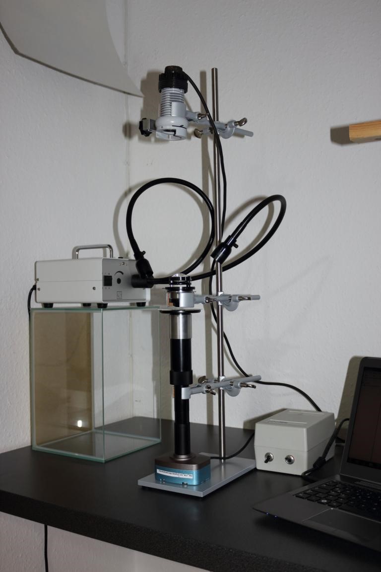
The chemical laboratory ring stand in this case functions as an optical bench as used in an optics laboratory, but with much less convenience and precision as professional optical benches have. All components have to be arranged strictly perpendicular on a common optical axis. The lowest standing part is the digital ocular-replacing camera with its eyepiece adapter pointing upward, followed by the inspection microscope turned upside down; then the stage with specimen on top; condenser; and the external microscope lamp in the uppermost position.
If a classical illumination system consisting of external microscope lamp and condenser is to be used, it is good to have a condenser with a long back focal length to get good hands-on access to your specimen resting on the stage.
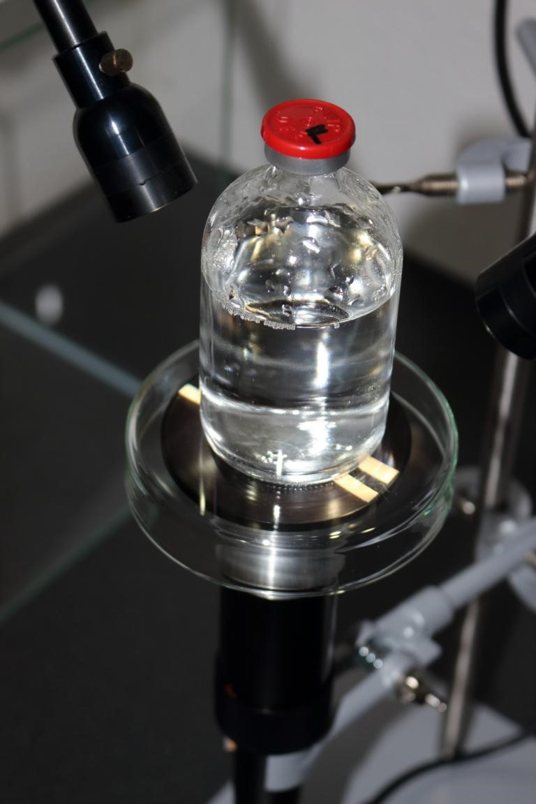
At this point, it may be a good idea to review the principles of correct Köhler illumination first before setting up this illumination system [1], [2]. Because of the easy access to all components in the illumination path (which is not the case with the usual upright microscopes of commerce), it is fascinating to see directly all elements of Köhler’s design for proper microscope lighting. I recommend the use of an observation screen made from glassine paper glued on top of an ordinary slide to get a good image of the lamp filament or the fringe of the field diaphragm when adjusting every component in the optical path. If condensers are used that are designed for upright usage, it is necessary to fix any filters (like color-temperature correcting blue glass filters) with the help of some short, transparent sticky-tape strips to the filter rest. Figure 3 depicts the vicinity of such a condenser setup above the slide with the specimen.

When the fiber-optic illuminator is used the condenser may be omitted and less care is needed for setting up the illumination system properly.
Use of the Instrument
Bottles, ampoules, vials, and other types of containers may be clamped to the stand directly above the stage. If the objects are large enough, such as cell culture bottles, they can be placed directly on top of the stage. Illumination is adjusted as appropriate for best visual results, for example, grazing angle illumination from one or two sides, perpendicular illumination with one arm of the fiber-optic illuminator, and so on. If preparations on microscope slides are to be inspected, the use of the external lamp with condenser above the slide is recommended to obtain higher numerical apertures of illumination. An example of a typical observation situation is given in Figure 4.
NOTE! Rounded ampoules and letters and numbers molded into the bottom of bottles can distort the final image. To eliminate or reduce this distortion, immersion oil may be used between the bottom of the vessel and the support slide; the immersion oil has the same, or nearly the same, refractive index as the glass and, so, makes the curvatures and legends invisible.
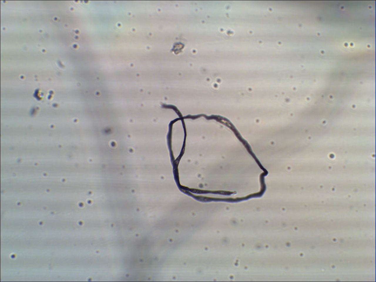
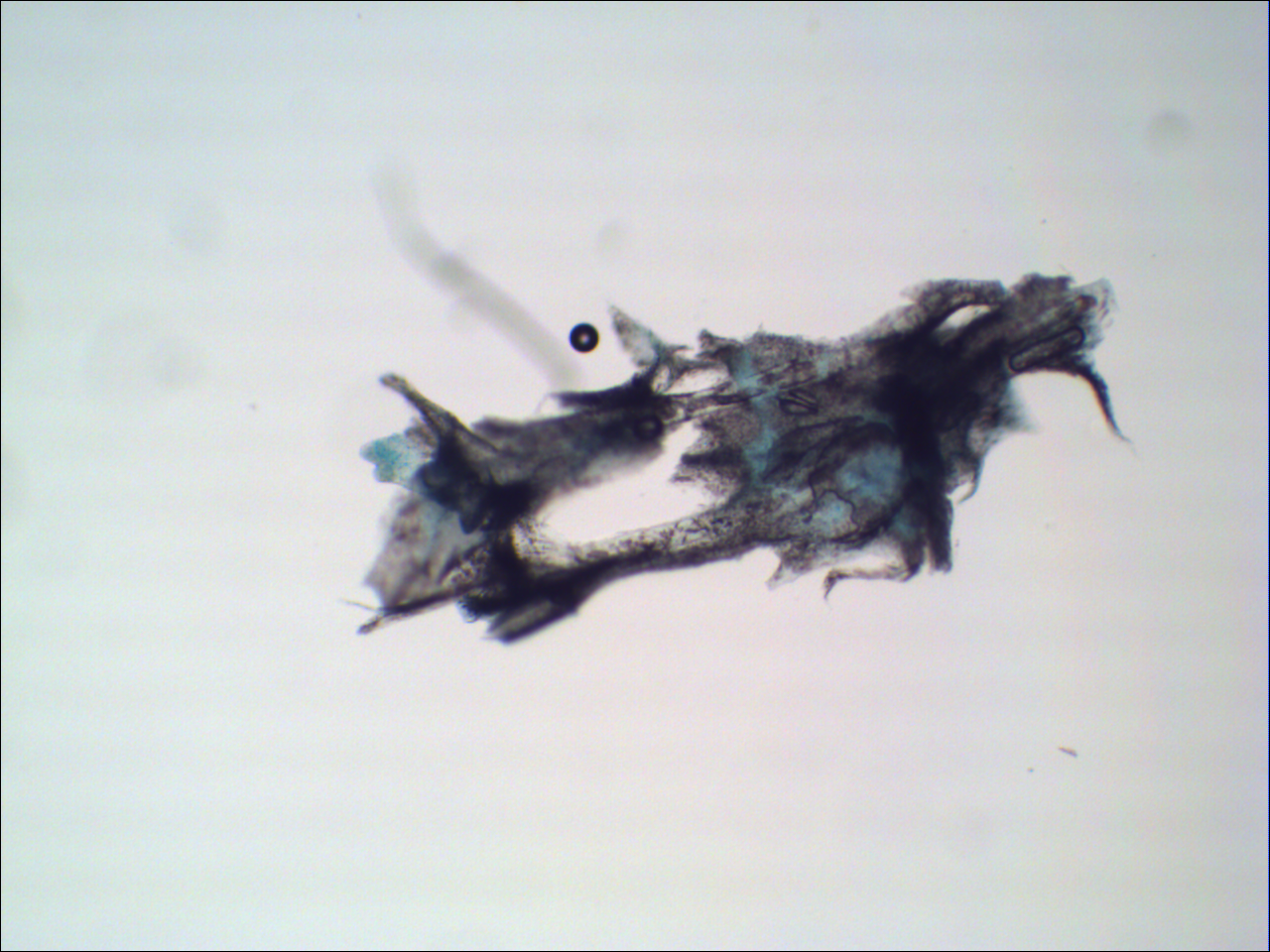
Control of focus (by turning a collar on the fixed microscope tube) and proper illumination is only possible by using the output from the digital camera, not by visual inspection using classical eyepieces; with practice the microscopist easily finds the optimum conditions. Figures 5 and 6 show examples of photomicrographs obtained with this improvised device.
Cited References
- Delly, John G. Microscope Illumination. Chapter three of Photography through the Microscope, Eastman Kodak Company, Rochester, NY, 1988.
- Köhler, August. Ein neues Beleuchtungsverfahren für mikrophotographische Zwecke. Zeitschrift für wissenschaftliche Mikroskopie, 10 (4), 1893, 433 – 440.
Acknowledgements
Many thanks to Dr. Allan Wissner, NY, for permission to use one of his photographs of an antique chemical microscope (see Figure 1).
Equipment used for the setup of the instrument described in this article:
- Inspection microscope of 160 mm mechanical tube length, Carl Zeiss, Jena, with achromatic objective 8/0.20 160/-
- Achromatic condenser, variable-focus, numerical aperture 1.2, Carl Zeiss, Jena
- External microscope lamp, fully centerable and focusable, with field iris diaphram, Carl Zeiss, Oberkochen
- Fiber-optic illuminator MKL 112 with double gooseneck light arms and focusable heads, Dr. F. Krantz Rheinisches Mineralienkontor, Bonn
- CMOS camera MCA-510, 5 megapixel, with image processing software Tsview 7, Fuzhou Tucsen Image Technology Co., Ltd.
- Chemical laboratory ring stand
Comments
add comment