Ways to Examine Metals by Light Microscopy
March 7, 2018
Presenter: Wayne D. Niemeyer, Senior Research Scientist, McCrone Associates
Light microscopy imaging techniques, such as brightfield, darkfield, and Nomarski differential interference contrast (NDIC), are used to examine metal surfaces and polished/etched metallographic cross sections. Grain size and shape, inclusions, and internal stress patterns are some of the common items of interest for light microscopy imaging of metals. Numerous examples are shown in this webinar. 36 minutes.
Transcript
Charles Zona (CZ): My name is Charles Zona, and I would like to welcome everyone to today’s McCrone Group webinar. Our presenter is Wayne Niemeyer of McCrone Associates. Wayne is a Senior Research Scientist with McCrone Associates who has over 40 years of experience in both electron microscopy and light microscopy. In today’s webinar, Wayne is going to talk about Ways to Examine Metals by Light Microscopy. Wayne will field questions from the audience immediately following the webinar. This webinar is being recorded and will be available on The McCrone Group website under the Webinars tab. Now I will hand the program over to Wayne.
Wayne Niemeyer (WN): Thank you, Chuck and welcome everybody. I certainly appreciate you taking time out from your busy schedules to join us today, so hopefully I can provide some useful information for you in examining metals by light microscopy.
These are what I call common light microscopy methods that we use for metals:
- Reflected (episcopic) illumination
- Brightfield
- Darkfield
- Crossed polarizers
- Nomarski differential interference contrast (NDIC)
The reflected light because they’re opaque, of course, and it’s also known as episcopic illumination, and the four types that I like to use are brightfield, darkfield, crossed polarizers, and Normarski differential interference contrast, better known as NDIC.
Now the brightfield, darkfield, and crossed polarizers are probably the most common illumination methods you’ll see in various publications and books, and so forth.
Normarski is a little bit less known, but certainly not here; I use Nomarski quite a bit, and I’ll show you some examples of these various illumination techniques. I’m not going into a lot of detail at all about the setups for brightfield, darkfield, and Normarski, and so forth, and the microscope accessories that are needed for things like that; I’m just going to give you the practical uses of these illumination techniques.
Here’s an example of some brown stains that were noticed underneath the clear coating on the inside of a food can. The clear coating was fortunate because we were able, then, to look through the coating down to the base steel—tin plated steel, and to see these brown regions that were causing the stain. Notice they’re circular; they have black lines going through them, and when I initially saw this, I thought for sure that these were starch grains. That’s a typical morphology of a starch grain; the black lines are known as isogyres.

We found out later through some analysis, by isolating some of these things from that can, that the material was actually iron carbonate. It was caused by some corrosion of the base steel underneath the tin that was oozing up onto the surface of the metal and oozing out underneath the clear coating to produce these features.
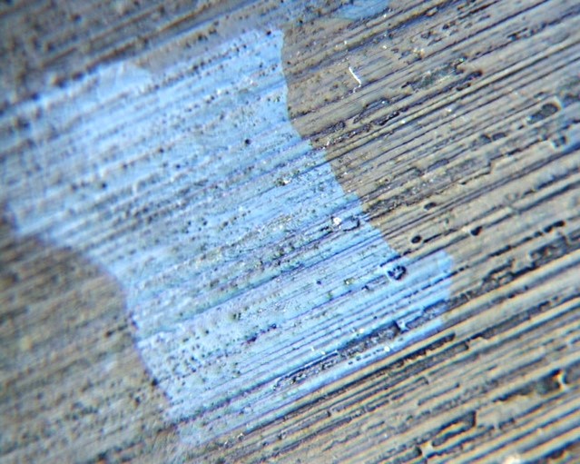
Let’s take a look at some contamination on tin plated steel. The surface of tinplate steel is quite smooth and bright, and in brightfield episcopic illumination it appears quite bright and you sometimes have to reduce the intensity of the illumination to see the structures a little bit better.
You can also insert a polarizing filter into the light path and that’ll help reduce some of the glare, just like it would from polarizing sunglasses that reduce glare on ripples and waves from a lake. But under the episcopic illumination, we see in the center there are two large very dark materials, and kind of in between them at the center the image is something that’s a little lighter gray, and then the rest of the surface is just the tin coating material.
If we cross the polarizers, now we can see a lot more information. The black material is now showing up as orangish-brown material and there’s a lot more of it—smaller features kind of scattered around that image—that we really wouldn’t even notice with the brightfield illumination. But the color of that material would suggest that it’s rust; iron oxide.
The center part of it (just to the left of center)—now we see that that lighter gray material is now kind of a bright white material under the crossed polarizers, so we can do one more thing: we can insert a first order red compensator into the light path, and that will also now allow us to see that these bright materials that are laying there on the surface are actually particulates that are crystalline materials; they are quite birefringent.
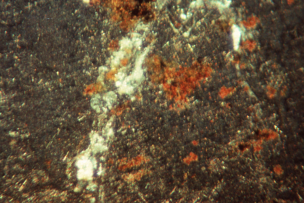
So, there are a lot of things that we can see with these types of illuminations that’ll help us identify or isolate materials for further identification.
Here’s an example of an electrolytic tin plated steel surface with crossed polarizers. Here we can see the tin grains; in fact, in the center there’s a large tin grain that’s kind of a bluish-gray color, and if we rotate the stage 90°, we can change that color into a blue color and then have the surrounding material be more of the gray material. This is oftentimes referred to as optical staining techniques to highlight various features on the surface of the metals that are anisotropic-type materials.
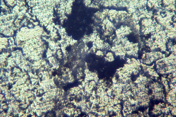
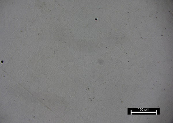
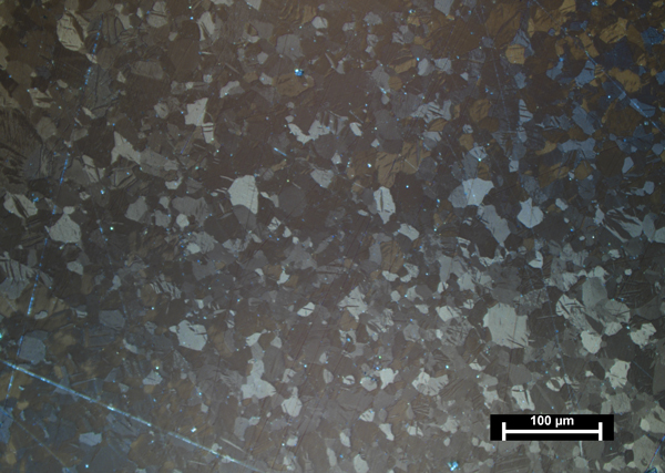
Here is an examination of some polished beryllium metal. With normal brightfield episcopic illumination—pretty featureless, not much to see there. It’s very reflective; even turning down the intensity of illumination to darken it a lot more, you can see very little material. But if we cross the polarizers, now we can see the grain structure of the beryllium. Beryllium is one of those metals that’s an anisotropic material, therefore, it will show up under the crossed polarizers with the grains that are in different orientations, and we can see the different colorations of the grains in those orientations. Now you can take an image like this—a digital image like this, and take it into some image analysis software and do some, perhaps, grain sizing or frequency distributions, percent coverage of specific size of the grains, and things like that.
So we’ll switch now from surface imaging to cross sections of the base metals of materials, and this is known as metallography techniques. This is where samples are cut out of the metal and mounted in an epoxy medium. Sometimes it’s a thermal set epoxy, other times it can be a two component epoxy that cures at room temperature. Then they’re ground and polished. They’re ground to get past the damage from the cutting area shown by the two arrows here—the two lines. We want to get past that cutting damage into the more pristine base metal, then we can final polish these cross sections, and perhaps even etch them like I have shown on the right-hand side here with the aluminum from this beverage can end.
The etching material here is 1% hydrofluoric acid. This is brightfield illumination, and you see the grain structure of the aluminum as it has wrapped around to the outside of the body hook, or flange, and back up inside the flange, and then it’s all pressed together. So we can see the strain structures of the aluminum as it’s going around these bending and pressing processes. You’ll notice at the bottom of the image there is a slight kink that has formed here, at the very bottom, and we can see that there’s some strain pattern going on, and this is a possibility now for some residual stresses that could be in this area that might eventually lead to a crack.
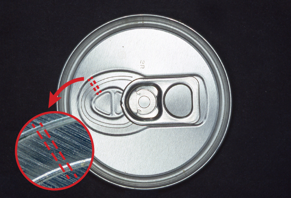
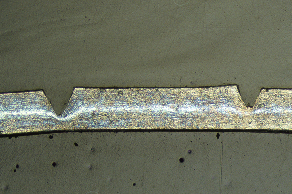
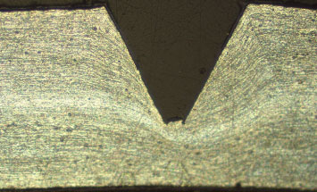
Again, on the aluminum end, we can cut through the score area of the flat— that’s what opens up the hole so that you can pour the liquid out when you pull that tab up. These score lines are there to have controlled fractures of that flap so that it fractures very uniformly around the circumference and folds down into the can. We cut a cross section through the score lines, and again, we can etch them with hydrofluoric acid, and we can see the flow patterns of the aluminum from that stamping operation to produce those score lines.
In the right-hand image, we can see that there’s a little notch, a little opening, at the very base of the “V.” That’s a potential site for corrosion attack—crevice corrosion attack—from the outside if the can gets involved with some sort of liquid on the outside of the end. These, again, are brightfield illumination with the 1% hydrofluoric acid etch.
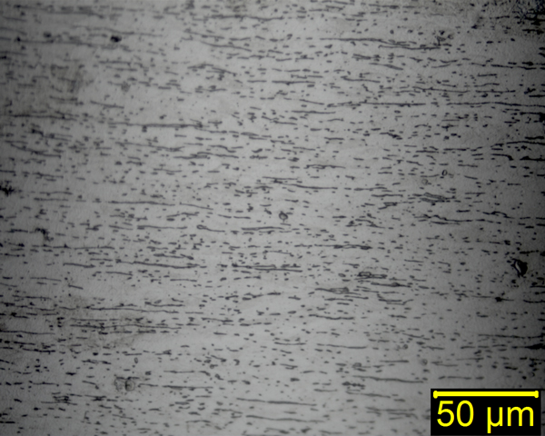
Here’s an example of brightfield illumination from a polished longitudinal section of a cold-worked carbon steel. This is 2% nital etch. Nital is nitric acid in methanol, and this is 2% by volume nitric acid in the methanol. That’s used quite often for carbon steel to highlight the grain structure so that we can see the flow of the grains, and so forth.
This is a longitudinal section, so we can see the elongation of the grains that occurred during the cold-working process to thin the metal sheet down to the final thickness. We can also see in here that there are some regions that look like they might be stringer inclusions in the metal, and those are often important to visualize.
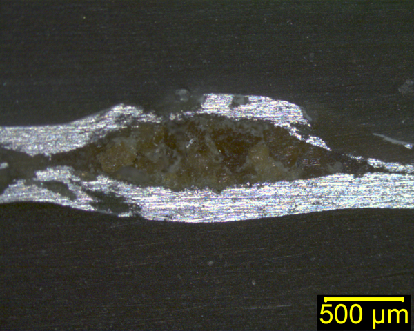
Here is one of my favorite cross section images. This is a polished aluminum sheet section, cross section, that has one huge, major inclusion in it. You can also see that around that inclusion the metal is already fracturing because it’s so big in there. Obviously, with the metal forming operation that these sheets go through, they encountered a lot of fracturing problems because of these inclusions. These inclusions were produced at the aluminum mill.
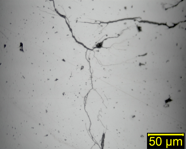
Here is a brightfield examination of a polished cross section of stainless steel that has very severe stress corrosion cracks. This river-like pattern that you see in there is quite typical stress corrosion cracking. This is unetched; we don’t want to see the grain structure so much—we’re more interested now in actually seeing the corrosion cracks rather than the grain structure of the metal.
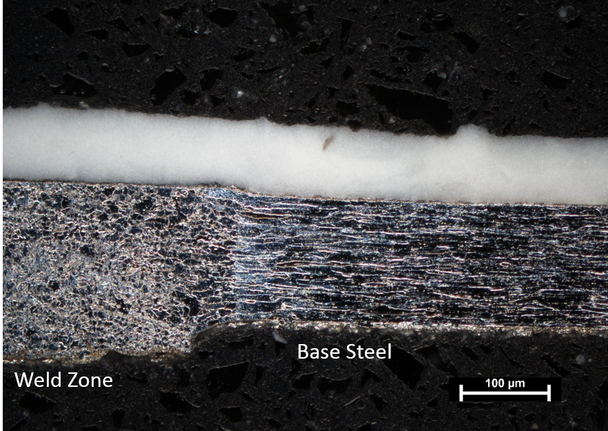
I am going to spend some time talking about this type of sample: it is a side seam joint weld from a tin plated steel food can. If you take a food can, like a soup can or something like that, and take off the paper wrapper, you’ll see that down the sidewall of the can there is a stripe that’s about a millimeter wide and dark gray. That’s the weld that occurs from the original sheet stock that has been rolled into the cylinder, and then overlapped slightly at the edges and arc welded to produce the final cylinder. Now the weld, in this case, is covered with an internal coating—that’s called the side seam stripe—to protect the weld from corrosion by the product that’s in the can. This particular can does not have a coating around all of the surfaces of the tin; only around the weld, and that coating is about a half inch or so in width to protect the weld.
In welding operations with metals, the weld will become very susceptible to corrosion attack compared to the surrounding matrix metal. In other words, in the electrochemical sense, the weld becomes anodic, the base steel metal becomes cathodic, and now when you have a corrosion reaction process starting, the corrosion reacts very rapidly within the anodic region; in this case, the weld.
Do you have a materials or packaging issue that needs to be resolved? Speak with a scientist.
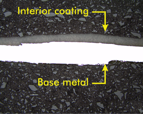
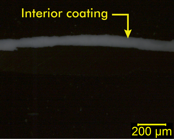
Here we have plane polarized light illumination; in other words, I have brightfield illumination with one polarizer in the light path to help reduce some of the glare, and we can see the base metal in the weld and the interior coating. Now if we cross the polarizers—and these are unetched again—now we can just highlight the interior coating if we want to by adjusting brightness and contrast, and take the metal out of the image, if we’d like.
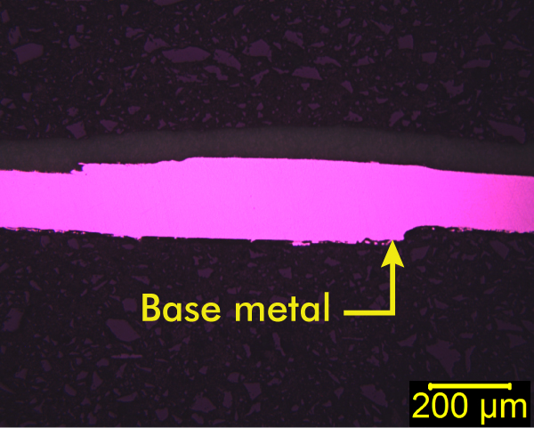
Or, we can go ahead and insert that first-order red compensator and just highlight the base metal itself, separate from the coating, and have the two side by side. It’s just a matter what you want to try to show as to the types of accessories and filters, and so forth, that you want to put into the system.
Let’s talk a little bit about Normarski differential interference contrast on that same side seam joint weld; again, it’s unetched. But when we use the NDIC we can highlight the base metal surface, and we can see very, very fine detail on the surface of metals with NDIC. In this particular case, we can see that there are lots of little scratch marks on the metal, and that’s from the polishing operation that was done on this one, and for the metallographers out there, if you look at this sample just visually after it has been polished, you’ll say “Wow, that’s a nice smooth mirror finish on that metal.” Put it under NDIC sometime and you’ll see that maybe it’s not quite as smooth as you thought. Actually, a good way to monitor the quality of your polishing operations is to look at it with NDIC.
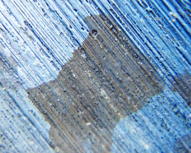
We can also use NDIC to colorize samples. The NDIC system has in the light path what’s known as Wollaston crystals, or Nomarski crystals, which are basically quartz wedges that are glued together, and we can move those wedges back and forth in the light path so that the light will go through different thicknesses of those two wedges to produce these different colorizations. So if we look on the right-hand side, the colorization contrast with the blue for the base metal, and now we can see that there’s another layer, where the arrows are pointing to, on top of that metal between the metal and the coating. That’s the tin coating; the tin plating showing up now that we can’t see any other way by the light microscopy techniques. This is the only way that I know of that you can really see tin coating that thin. Tin, being an anisotropic metal, will show up because of the crossed polarizers, and this will help highlight it.

If we take that same area and just increase magnification from left to right here, we can highlight that tin plating layer a little bit more, and we can see that it’s approximately 2 µm thick, so that’s pretty thin for looking at it by light microscopy. It’s actually better to look at it by scanning electron microscopy. But, we can certainly see it in this imaging technique with NDIC. Note also that in the blue colorization layer we’re not seeing the scratches so much from the polishing, and that’s because of the way it’s colorizing it.
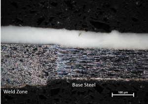
So now let’s take the same weld and let’s etch it with the nital—the 2% nital. On the left-hand side, we have the plane polarized light illumination and we have the weld zone, which is highlighted here: you can see that much different crystal structure, or grain structure, of the weld area versus the surrounding base metal to the right and left of the weld. Then the inside side seam protective polymer coating is still there, but we can barely see it in these particular images. That weld zone is also referred to as a heat affected zone in welding terms. On the right hand side we have a higher magnification image of the weld zone under the plane polarized light so you can see the grain structure much better. It’s a very complex grain structure, for sure, compared to the elongated grains that are in the base metal next to it.
Now we can do some other things. On the left we have the plane polarized light again, and on the right—now we’ve crossed the polarizers. Now we can see a couple of things that really jump out at us.
First of all, that internal protective coating is now very bright white. The protective coating has fillers and pigments in it that are quite birefringent materials, and that’s why they show up so well now with the crossed polarizers.
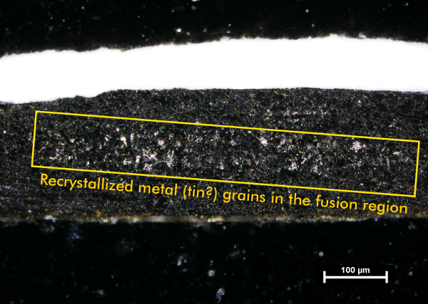
I want to draw your attention to what’s happening within that yellow box. We can see that there’s evidence of recrystallized material in that fusion region of the weld. This is where the two overlapping pieces of the tinplate have been melted and welded together. I suspect that the recrystallized material that we’re seeing in there—from the birefringence with the crossed polarizers—is probably from the tin that melted during the welding process and diffused into that fusion zone from both of those plates as they were welded together. Tin, again, is an anisotropic metal; the iron base steel is not. That’s what I think that is; it’s probably recrystallized tin grains in that fusion region.
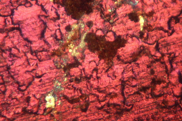
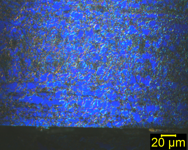
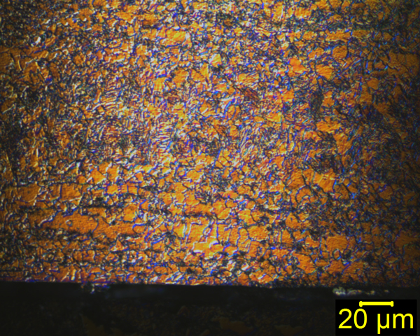
We can also go to colorizing the features in here with the etch. We can colorize it blue like we have on the left, or we can colorize it mainly with orange, on the right. Here we can see that there are different—perhaps phases present, especially in the blue. From my eye, I can see that a little better with the blue. There is a dark kind of webbing type net in the structures that is interwoven in there amongst the flatter grains in the sample. So, here you can take these images, digital images, and put them into some image analysis software, and perhaps do some analysis for percent area coverage of the phase that is represented by the web-like material, something like that.
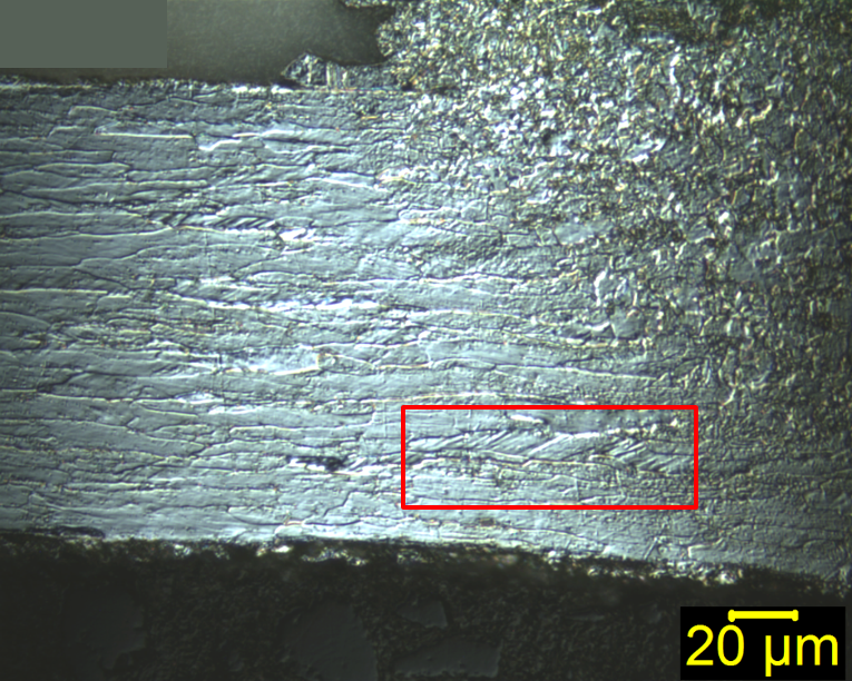
Let’s take a look now at the base steel versus the weld zone, and the structure of that material. On the left-hand side we have the plane polarized light illumination. Then we can increase the magnification a little bit more and look at it with NDIC. Notice the NDIC is giving you some three dimensionality perspective of those weld grains from the etching process. NDIC is really, really good for topography information on reflected opaque subjects like this. It’s normally used in transmitted light mode for biological samples, for cell structures where you have very little contrast; the transmitted light Normarski differential interference contrast gives you much better contrast on low-contrast-type materials. But, in metals or surface imaging like this, we are actually seeing topography differences, and that can become very useful.
Note also in the NDIC image that all the little scratch marks that we saw earlier with the NDIC unetched are gone. The etching does remove those very fine scratches. It’s dissolving the surface away and penetrating down into the grains of the metal. You can also use this as sort of a quality test on your metallography to find out if you’ve actually removed the scratches and gotten away from the surface, and gone down more into the base metal.
I also want to bring your attention to the detail that this can bring up. Look inside the red box here, you might not be able to see it too well, but there’s a grain in there that has parallel structures spaced at about at a 45° angle, and spaced only a micrometer or two apart from each other. Very, very fine detail that you can see with NDIC that you’re just not going to see in any way other than light microscopy.
Now we can continue on and take a look at what darkfield illumination presents for us. On the left we have our plane polarized light, and on the right is the darkfield illumination of the weld zone. Here we can see the grain structure outlines very easily—the nice light outlines, and then the dark regions are the flat regions of the grains that are reflecting directly back up to the objective and to the eyepiece. Those reflections coming directly back up are actually blocked in the objective system, so that we wouldn’t see that. We’re seeing the scattering of light due to angles and topography differences, and so forth. Anything that’s really flat is going to look quite dark.
We can also see the protective coating is a nice bright white; we can see that much more clearly at this point. But again, these things can be used, then, for other imaging manipulations with software, and so forth, if you are trying to do some quantitative work with that.
I am going to finish up a little bit here to give you four different images of the same region—the same field of view—using each of these four techniques to show you what they can really tell you.
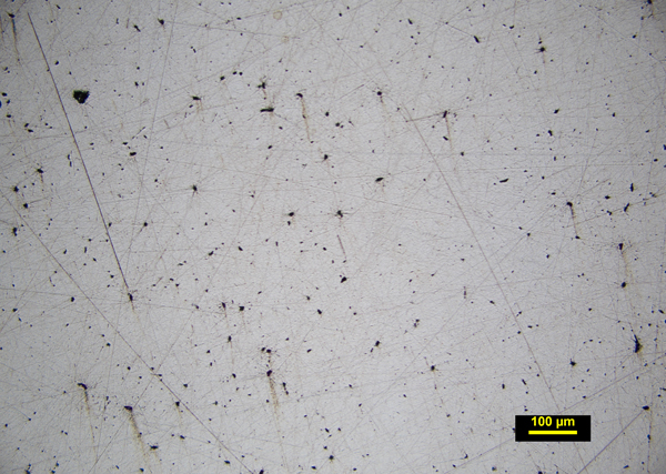
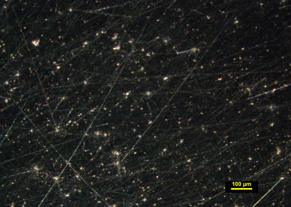
Here’s a polished brass. It’s final polished with 1 µm diamond paste slurry, and the brightfield illumination is what most metallographers would be looking at to look at their polishing system. We can see that this one is not polished quite well enough yet. Some of these dark specks have what we call “comet tails” coming off of them like they are smeared a little bit; a smearing action. We can also see some heavier scratches that also are kind of parallel to these little smearing things. This sample needs to be polished a little bit more. It hasn’t removed all of the artifacts from the previous grinding and polishing steps before it got to the one micron diamond paste, but it illustrates what you see with this type of illumination.
Let’s go ahead and cross the polarizers. Well, there are our scratches, again. For the metallographers out there, if you’re looking at how well you’ve done, you may not want to look at it with crossed polarizers because it will be a sticker shock for you compared to the brightfield system, but it certainly can be used as a quality test for how well your polishing has been going.
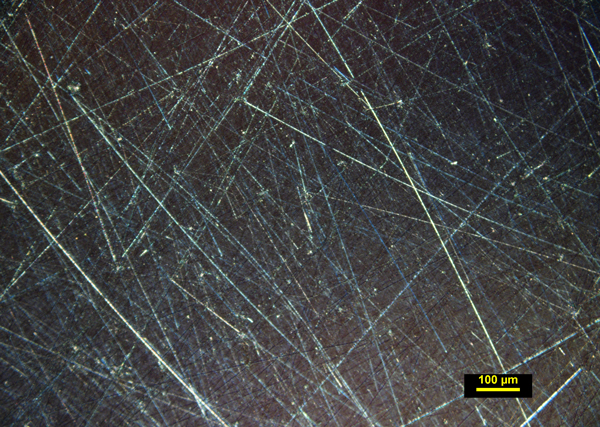
If we take a look at it with darkfield illumination, we don’t see the scratches quite as much, but it’s really highlighting all the little inclusions that are on the surface or within the surface of that metal. Now, you can take something like this image and take it offline into an image processing software and do particle sizing, particle distribution, particle frequency, you can do particles per unit area, and things like that to help characterize the sample.
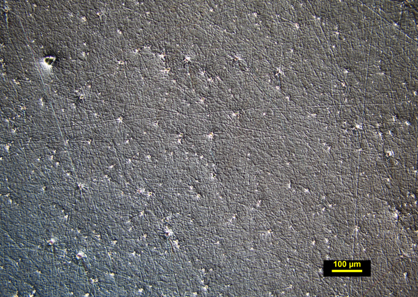
Finally, if we look at it with NDIC, you can see now that we can really see the very, very fine features from the polishing operation, and we can also see some of these inclusions that are still there, but not quite as well as we could with darkfield—but if you really want to see very fine detail on the surface of materials that are highly polished, NDIC is probably the way to go so that you can really see what’s going on on the surface.
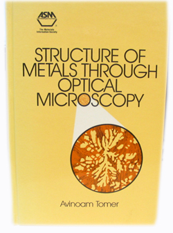
I want to close with giving you some references that you can look for. If you’re still interested in optical microscopy of metals, this is a great reference book: Structure of Metals through Optical Microscopy by Tomer, copyright 1991 by ASM International. It’s probably not available now. I did not check it on the ASM website. This is an outstanding book because the author goes through some preparation techniques, metallography preparation techniques, optical microscopy stuff, different alloys, different cross sections from metal forming, deep drawing operations, welding operations, other joining type systems, and so forth. It’s a very, very good reference book for all kinds of different things. If you are a generalist working with different types of metals, alloys, and so forth, and want to compare what they look like under light microscopes, this is an outstanding resource for that.
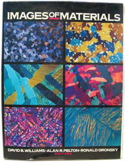
Then we have the book Images Of Materials. This is copyright 1991 by Oxford University Press. It’s edited by Williams, Pelton, and Bronsky, and there are various authors that have contributed to this book. The first chapter is optical microscopy of metals and it is written by George Vander Voort. George is a world-renowned expert metallurgist, metallographer, fracture analyst, and so forth, and he does a lot of webinars also for these types of things. He’s an excellent resource. The first 50 pages are his chapter, and then after that it has all kinds of images from different techniques: scanning electron microscopy, transmission electron microscopy, and X-ray diffraction, and so forth; lots of different material images by various other instrumental techniques. Another outstanding reference book.
Finally, this is one of my favorites. It’s an old book copyright 1972 by the American Society for Metals, or ASM International as it is known now. It is the Metals Handbook Volume 7, Atlas of Microstructures of Industrial Alloys. This particular book has all kinds of different alloys and is just loaded with pictures of microstructures, surfaces, and cross sections, and so forth. ASM International now produces books like this, but they are more geared for specific alloy materials. There might be books just for zinc alloys, and other books for copper alloys, and other books for steel alloys, and so forth, which is fine, and they are more up-to-date of course, but this particular book has them all. It has tons of different materials: refractory metals, stainless steels, nickel alloys, copper alloys, titanium alloys, electrical contact materials, carbon steels, steel castings, and tool materials—everything all in one book. It is an absolutely outstanding book. If you want to get it, you probably will have to find something on eBay, because I know ASM doesn’t publish this one anymore.
So, thank you for joining us today, and you can start putting your questions in the chat box if you haven’t already done so.
CZ: Yeah, we will start taking questions here, just go ahead and type them into the questions box, and Wayne will start going through these:
Question: “Could you please explain more about stress corrosion cracking?”
WN: Stress corrosion is caused by, obviously, a corrosion reaction on metals that have been stressed in some way or another. They’re either bent, or they’re deep drawn, things like that, where they’re not in the normal relaxed position. Those stress areas are going to be much more susceptible to corrosion attack. When the corrosion attack starts, it doesn’t just go around the grain boundaries; it goes right through everything—all the grains, and so forth. It’s a very rapid cracking mechanism. It only occurs, of course, with metals that are under a stress load of some sort.
Q: “Can Normarski be retrofit to a standard light microscope?”
WN: I guess it depends on the microscope—if the Nomarkski accessories are available for it. You’d have to check with the microscope manufacturer for that, but certainly it can. It’s going to have to be a compound microscope, though, not a stereomicroscope.
Q: “What kind of configuration is needed for NDIC?”
WN: There are accessories for the NDIC. You’re going to need the Wollaston prisms to be inserted into the light path, and you’re going to need the polarizing filter and analyzing filter along with it to do the cross polarization that you need to do with NDIC. Again, those are things to check with your manufacturer to find out what accessories you are going to have to have, but that would be the basic setup for it.
Q: “For cross polarization, are the two polarizer filters upstream of the sample, or downstream, or what? How are the cross polarizers planned in the optical transmitted path, and does it matter which one rotates?”
WN: Typically, and certainly in transmitted light, one polarizer is put underneath the sample, and then the light comes through it and passes up through the sample, then the analyzer, which is the other polarizing sheet, is up in the light path leading to the eyepieces. In reflected light, there is a polarizing filter inserted into the light path, and then the analyzer is placed elsewhere there, and you rotate the analyzer. The polarizing filter is generally fixed in place and then the analyzer is rotated versus it.
Q: “I joined a little late. I do PLM fiber identification and I am new to NDIC. Is it something software based, or just accessories based?”
WN: It is accessories based. It is something that you would use in the microscope to take images of your samples from there. It’s actually pretty good for fiber use, looking especially at the natural fibers, to look at the surface structure of natural fibers.
Q: “Do you have a particular brand of microscope that you use?”
WN: The microscopes that I have in my office are Olympus. My polarizing light microscope is the Olympus BX51.
Q: “Which method would you recommend to highlight transfer of metal from one source to another via contact?”
WN: I presume you’re talking about transfer of material from the metals as they make contact, if they scraped against each other or something like that. Certainly, you look at light microscopy first, that’s usually always the first thing that we would do, and then you can put it into—if you can—you can get it into an scanning electron microscope, and get a little more detailed information about it, and perhaps elemental analysis of material that has been transferred from one to the other to try to verify if that material was consistent with that metal having touched it.
Q: “Could image software like Photoshop be used to identify percent carbon in steel, ultrahigh carbon steel?”
WN: No, not that I’m aware of. To identify the percent carbon in steel, that generally has to be done by other instrumental methods, not by light microscopy.
Q: Someone else has a BX51. “Are there NDIC accessories available and compatible for it?”
WN: There certainly are, because I have them on mine. So, yeah, those accessories are certainly available. McCrone Microscopes & Accessories would sell that type of thing for that microscope and also for the Nikon microscopes.
CZ: I think that’s about it. I think you got through all of the questions, Wayne, lots of good questions out there. Definitely go to our McCrone Microscopes & Accessories webpage or contact one of our sales representatives. They would be happy to help you out with some of the accessories that Wayne was talking about. We hope to see you, then. Thanks.
Comments
add comment