About the Use of Digital Single Lens Reflex Cameras on Microscopes
For micrography a choice between dedicated microscope cameras and single lens reflex cameras (SLR) has long been available. This choice exists not only for film based but digital documentation as well. For some time I have experimented with a digital SLR (DSLR) on my microscope and found it to be a valuable instrument for taking satisfying, well resolved micrographs. In contrast to many of the dedicated microscope digital c-mount cameras, which typically are tethered to a computer, the use of a computer with a DSLR is optional. In regard to portability, this is obviously an advantage. But it is also a liability because the use of a computer is limited to viewing and editing the images after capture, whereas the dedicated digital microscope camera offers convenient ways of enhancing images before they are ever recorded. This paper deals with some of the specifics of a DSLR that must be considered to take advantage of its capabilities.
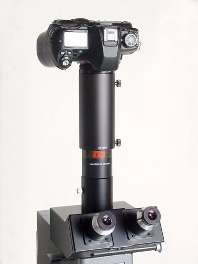
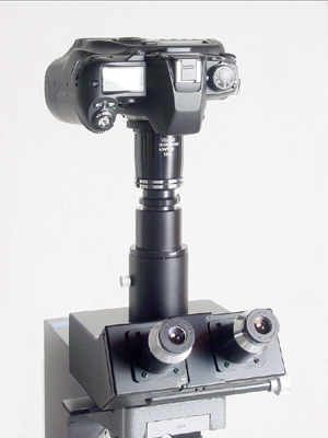
My point of reference is a Fuji Finepix S2 Pro. I limit this article to the generalities applicable to any DSLR or SLR. Typically, today’s DSLRs are built around proven SLR bodies where, after pressing the release button, the mirror flips up and the focal plane shutter exposes the chip for the chosen length of time. A connector tube joins camera and microscope rigidly, and that can be a problem. The motions of mirror and shutter cause the microscope to vibrate so that the microscope objective moves relative to the specimen. If that motion were just a micron in the specimen plane, the magnification may amplify it 1000 times or more when it is displayed on the computer screen or print. This causes blurred images with all except low magnifications. Experiments show that locking up the mirror does not solve, or even significantly reduce, the problem. There are two proven remedies that I know of:
- It is immune to vibration problems. Use of long exposure times. The vibration that occurs when the shutter opens lasts for about 1/30 second. If the exposure time is long relative to that, the initial vibration becomes insignificant. I have methodically tested several SLRs and found an exposure time of 1 second or longer to be safe at any magnification.
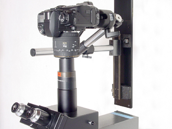
- Mounting the camera to a wall bracket with a gap between the camera and the microscope so that the two are not mechanically connected. This requires the use of a camera lens on the DSLR, which “looks” into the photo eyepiece of the microscope. The eyepiece projects an image at an infinite distance which the lens of the DSLR, set to infinity, ”sees” it as if it were a distant landscape. This approach has several advantages:
- It permits the use of a standard camera lens containing the necessary microprocessor to allow auto exposure.
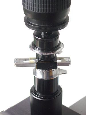
- Finally, it permits the use of image reticles, cross lines, scales, grids, etc., which are installed in the photo eyepiece.
Compared to the 35mm format the chip of typical DSLRs covers about 40% of the area. To capture the same field with a DSLR as with a 35mm SLR, either the magnification of the photo eyepiece or the focal length of the camera lens must be smaller by a factor of 1.6x. There are a couple of full frame (24 x 36mm) DSLRs made for very demanding uses to which this precaution obviously does not apply. On the opposite end there is the emerging Four Thirds standard for digital system cameras with chip dimensions of 18 x 13.5mm. Here the area is 28% of the 35mm format. The diagonal is exactly half that of the full frame 35mm format and to capture a comparable field the magnification then needs to be smaller by a factor of 2X.
Now, the diagonal of a chip 15.5 x 23 equals 27.7 mm. 27.7 divided by 3.2 = 8.7. The chip diagonal represents a FN of 8.7mm. With an 8x eyepiece and camera lens 0.32 the product becomes 2.5. The FN increases to 10.9 mm etc. I usually would not attempt to capture more than FN 15 because larger fields, especially when low power objectives are used, contain an amount of information that may exceed the camera’s resolution capabilities. Also the likelihood of shading increases with the FN. Shading is the technical term for a falloff in brightness toward the edge of the image. This is a good place to consider the purpose of the photo eyepiece and camera lens. Together they control the size and magnification of the captured field. Present microscopes have field numbers (FN) of 20 to 25 mm. The FN is the diameter of the image in the intermediate image plane (IIP) that the eyepiece reveals. How much of that field is actually captured by the camera depends on the product of the magnifying power of the optical components following the IIP, which are the eyepiece and the camera lens. If the eyepiece were of 10x and the camera lens of 0.32x power, the product of the two, 3.2 would be the magnification of the intermediate image in the plane of the chip.

Sometimes the eyepiece and camera lens are fixed, inseparable components of the photo adapter. Sometimes manufacturers omit the camera lens altogether by bringing the normally parallel rays emerging from the photo eyepiece to convergence in the camera’s image plane by lifting the eyepiece out of its sleeve by a certain distance and sometimes that distance is already added to the eyepiece’s shoulder which then should be called a projective. In all three scenarios it makes sense to engrave just the magnification that takes place between the IIP and the chip, 2.5 or 3.2 in our example.
Typically these microscope adapters end with a T-mount thread on the top. Additional conversion adapters are needed (available from camera stores) to change the T-mount into just about any camera-specific bayonet mount. The limitation of these adapters is that they lack the microprocessor and electrical connections to activate the automatic exposure timing. While it is not difficult to determine the right exposure time by trial and error in manual mode, it is possible to restore the auto exposure function by using one of the lenses made for general use with the particular camera model. The aperture of the lens is set to its maximum f-stop and aperture priority chosen as the exposure mode. The magnifying power of a camera lens following the eyepiece can be calculated by dividing 250mm into the focal length. A 50mm lens, for example, has a camera lens factor of 0.2x. Conversely, the 0.32 camera lens mentioned a couple of paragraphs earlier has a focal length of 80mm.
Without the help of a machinist it is difficult to integrate that camera lens into a rigid connector. That is another reason why I like mounting method 2 mentioned earlier. This configuration also permits to alter within limits the distance between eyepiece and camera lens. That may be desirable to avoid hot spots and, especially in the case of zoom lenses, to find a distance where eyepiece pupil and lens pupil share a common plane to eliminate, or reduce, vignetting. Generally, the longer the eye relief of an eyepiece is, the better. The rays emerging from the eyepiece form a hourglass-like cone, which can be made visible by letting the light graze a piece of paper. The vertical distance from the top of the eyepiece to the waistline of the hourglass is called the eye relief.
The auto-focus is not reliable in micrographic applications; it should be disabled. A DSLR would not, under some circumstances, be my first choice on the microscope but as a workhorse for the widest range of uses on or off the microscope, it is indispensable and it would be a shame not to tap its terrific potential. At six mega pixels the chip is not a resolution-limiting factor in micrography and the large pixels (compared to the point and shoot variety of digital cameras) favor a superior dynamic range. At exposure times of up to 30 seconds at 100 ASA equivalent the sensitivity is sufficient even for most fluorescence images.
I would not easily part with my DSLR, and to tame it for use with the microscope was well worth the effort.
Comments
d de backer
how to calculate the "camera lens power" mentioned above (an said to be 0,32).
Its unclear to me
thanks for reply.
Replies
John Gustav Delly
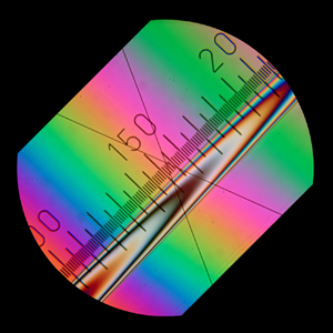
You don't calculate the “camera lens power"..... it is determined by the lens placed in the photomicrographic attachment by the manufacturer. Just attaching an empty tube between the microscope and camera almost always results in a vignietted image or one of much higher final magnification that does not fill, or overfills, the 35 mm frame of the camera. In the past, in the Leitz "Mikas" photomicrographic attachment, for example, the intermediate tube that goes between the microscope and camera could be ordered with built-in lenses that resulted in "camera lens power" of 1X, 0.5X, OR 0.33X magnification.....the most common being 0.33X. In calculating the final magnification on the negative, using the 0.33X attachment with a 10X objective and 10X eyepiece, you would multiply 10X x 10X x 0.33X = 33X on the 35 mm film. These intermediate lenses are minifying...that is, negative lenses...that reduce the combined magnification of the objective and eyepiece. That way, using the 0.33X attachment, an enlargement of, say, 3 times on a print would result in a print image that was close to the original microscope magnification. In actual practice, these intermediate reducing lenses are installed via a threaded mount, so there is some small variation allowance in its exact position, resulting in small departures from the expected magnification. For this reason, it is absolutely necessary to make a photomicrograph of a stage micrometer, and actually measure the "true magnification" on the film. The nominal reduction factor is almost always engraved somewhere on the photomicrographic attachment in use...this is the number you use to multiply your microscope total magnification to obtain the magnification on your film. 9 cm x 12 cm format photomicrographic attachments often have a 0.5X “tube factor” by which you multiply your microscope magnification to obtain the final magnification on the larger format film, which was commonly contact printed, or enlarged 2X; but, again, it is necessary to photograph a stage micrometer, and measure it directly, to obtain the “true magnification” on the film. The lens built into the photomicrographic attachment mentioned in the online article reduces the microscope magnification on the film by 0.32X, according to its manufacturer. Of course, if you are using a photomicrographic attachment with no camera lens power engraved on it, you may photograph a stage micrometer with your microscope visual magnification set up for 100X, and measure the scale on the film to obtain its actual magnified size to obtain its "camera lens power."
add comment