Meaningful Particle Analysis Begins with Light Microscopy
April 11, 2017
Presenter: Bill Chapin, Senior Research Microscopist, McCrone Associates
An understanding of lighting sources and even modest particle manipulation skills can unlock a new understanding of particle identification. Macroscopic observation of dark particles may reveal that they have distinctive shape/color or that the particles are heterogeneous rather than homogeneous, etc. Various light sources and their use will be discussed as well as a few teases about particle preparations that create homogeneous samples for instrumental analysis from heterogeneous samples. This webinar focuses on the powerful use of stereomicroscopy–the beginning point of nearly all of the particle analyses performed at McCrone Associates. 59 minutes.
Transcript
Charles Zona: Welcome to another McCrone Group webinar. My name is Charles Zona, and today our presenter is Bill Chapin. Bill is going to talk to us about meaningful particle analysis and how it all begins with the light microscope, in particular, the use of the stereomicroscope. Before we get started, I would like to talk a bit about Bill’s background.
Bill is a senior research microscopist at McCrone Associates with more than forty years of experience in trace evidence and particle identification. Prior to coming to McCrone, Bill spent more than twenty years at the Johnson County Crime Lab in their trace evidence section. Bill has taught a variety of courses at Hooke College of Applied Sciences, including Advanced Polarized Light Microscopy, Introduction to Forensic Trace Evidence, and Pharmaceutical Materials and Contaminants.
Bill will field questions from the audience immediately following today’s presentation. This webinar is being recorded and will be available on The McCrone Group’s website under the webinars tab, and now I will hand the program over to Bill.
Bill Chapin (BC): Hello. I just took a look at some of the names here on the attendee roster, and I see a lot of people that I know, and that puts me at ease because I’m doing this live and I was a little afraid I was going to freak out.
Anyhow, my name is Bill Chapin and I have been working with light microscopy for decades, actually. Any of you who know me, know that light microscopy is my go-to technique. I really think that there are a lot of people in industry that are not utilizing the light microscope as much as it could and should be used. I think light microscopy lends itself to improved analyses and better sample preps. If you have any questions as I’m talking, go ahead and type them in. We’ll see them, and if it’s something relevant to what I’m speaking about at the time, I will try to take those questions and answer them on the fly.
We’re going to start by talking about equipment and tools. We’ll talk about the stereomicroscope, polarized light microscope, and illumination techniques. Quite a bit of time will be spent talking about and emphasizing illumination techniques (too many techniques are not taken advantage of and effectiveness of the microscope is lost). Then we’ll talk about a few sample-handling tools, because it requires a different “tool box” than is used for macroscopic techniques. For the last half or more of the discussion, I am going to show you situations when the light microscope may make a more positive identification than other instrumental techniques may, such as micro-Fourier transform infrared spectroscopy (FTIR) or scanning electron microscopy (SEM) equipped with energy dispersive x-ray spectrometry (EDS). There are times when these instruments only provide class information. We will then spend time with sample preparation prepared under the stereomicroscope.
We’ll create a homogeneous sample from a heterogeneous material, and do some other fun isolations and sample preparations.
I want to point out that the examples I’m using should be thought of as springboards for other analyses that may be similar. For instance, when I’m talking about cross sections of paint, some of you may want to talk about, or be thinking about, cross sections of plastics or some other material. When I’m talking about surface texture of paint, or surface texture of plastics, there may be some metals applications where you’re wanting to look at surface texture. Try to take my techniques and apply them to your specific areas of interest.
The standard stereomicroscope is not really standard; it’s a pretty beefed up instrument. It’s basically no different than one you might have used in high school biology, or perhaps biology or entomology in college, but we’ve added a lot of things to it. Let me get my little laser pointer here. We’ve added multiple light sources (illumination sources) and additional filters. There are two objectives: a 1.0X objective and a 0.5X objective, and a port up here for a camera.
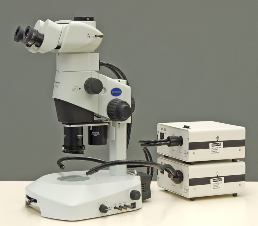
In my opinion this design is really what’s necessary for an optimally-equipped stereomicroscope. The other ‘scope we’re going to talk about is a polarizing light microscope that many of you are familiar with. It has set magnifications that are dependent solely on the objectives and the eyepieces you install. You can buy several nosepieces and put up to six objectives on most PLMs. Typically, you’re going to have a 40X objective, or, excuse me—a 4X objective, a 10X objective, maybe a 20X, maybe a 40X, so that you can go up to 400X magnification. 500X is nice if you want to look at interference figures–we’re not going to go into interference figures today—but 500X is a nice use for them because of the higher numerical aperture. In my applications here at McCrone, there are times when I need to look for bacteria, so we have 100X objectives and can go to 1000X magnification with immersion oil. The stereomicroscope is somewhat different in that it generally has a fluid zoom magnification range with a lower magnification: 5X or 10X to 100X, to maybe 135X. Some ‘scopes will have a click-on or click-off device associated with the zoom magnification; that’s useful if you’re going to take photomicrographs. Engaging the click stop ensures consistently locked magnifications within the fluid zoom range. This allows for use of a specific magnification and addition of an accurate scale bar to photomicrographs.
Oblique illumination is most commonly thought of in conjunction with a stereomicroscope. The light comes from the sides at an angle. Here, you can see there are two bifurcated light sources whose angles can be changed to increase or decrease the angle the light impacts the target object. Sometimes a very severe raking of the light may be necessary, as in the case of looking for colorless fibers or other colorless particles on a filter. In another situation, it may be advantageous to pull them up and bring the light more directly down from the top. Another adaptation is to put a ring light, which is considered oblique illumination, on the objective in use. Ring lighting has some limited uses and should not be confused with coaxial illumination (discussed later). When it is useful, ring lighting is great. Sometimes, it just doesn’t help so you just get rid of it. It is often forgotten that oblique illumination on a polarized light microscope is also very useful, most notably when looking at color or other non-transparent particles, perhaps in the case of a fugitive dust or a dirt sample that has various different colors of paint in it, or it has some white spheres as well as black spheres, things like that. Through the use of oblique illumination, you can see the color and learn a lot more about your sample.
When discussing transmission illumination, that’s when we typically think of a polarized light microscope. The light comes up from the bottom, through our specimen, and is seen through the eyepieces—it’s transmitted; it goes through the specimen. One thing that people often forget is that this type of lighting will change the color of some particles, particularly when looking at fibers. You may look at a fiber with oblique illumination and it’s a purple fiber; when you look with transmitted illumination it may be more pink, or it may be more maroon. It’s going to have a color shift because of the way the light is transmitted through it instead of reflected off of it. Some people do not recognize the value of transmitted light on a stereomicroscope. I think it’s invaluable. It’s exactly the same concept as on a polarized light microscope; light comes up from the bottom, through your sample, and to the eyepieces. It is particularly useful if you’re looking for particulate in a colorless container—maybe a medical device like an IV bag, or a vial, things like that—where there is free-floating particulate in a transparent liquid. Often the particulate may be seen much better with transmitted illumination than with oblique illumination.
What I would submit to you is that we can take the stereoscope further and really enhance it with transmitted illumination. I will take it a step further and drop a polarizer right here in the light path before the light passes through the sample, so we’ve created transmitted polarized light just like we do over here in the polarizing light microscope. Now the lighting becomes a little different. There is a quarter-wave plate on the objective that is in place for coaxial illumination, which I’ll talk about next, but it’s the compensator that’s already on the microscope that acts as an analyzer. Now when you look at your sample you can get a partially cross-polarized illumination system, so that you can still observe birefringence and some different lighting effects from specific particles.
Let’s say you’re looking at a soil sample and you’re trying to find glass. You can very easily use this to locate isotropic glass particles and separate them from the anisotropic quartz particles. The quarter-wave plate acts something like a traditional analyzer in the polarizing light microscope, but it’s a pseudo-cross polarization technique; it doesn’t have the full effect of fully crossed polarizers that you would see on the polarizing light microscope.
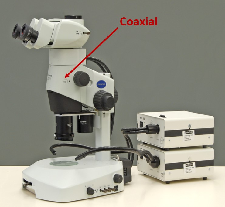
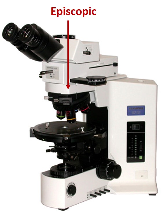
Now let’s look at reflection techniques—the most underused and most powerful lighting technique, particularly for pharmaceutical products, that really needs to be on your stereomicroscope. Reflection is different from oblique in that it comes straight down from the top, hits your sample, and bounces back up and into your eyes. The same way with the polarizing light microscope, it comes from the top, down, and bounces back up. So, it’s a reflection technique off the particle surface. When you’re dealing with a stereomicroscope, this technique is called coaxial, because there are two different light axes in the stereomicroscope. The similar technique on a polarized light microscope has a single light axis and is called episcopic. There are some technical differences in how they create the effect of what you see, but they both produce the same observation of materials. We’re going to take a look at the uses of coaxial/episcopic illumination, and I will say that there is virtually never a sample that I don’t use coaxial or episcopic illumination on. We will see some of those applications in a minute, in some of the examples I’m going to show you.
Let’s talk about our toolbox. Down here in the lower left is an array of tools that I’m going to be using in this presentation. There is a tungsten-carbide scribe, a micro scalpel, three tungsten needles, and two sets of tweezers—one curved and one straight. These tweezers are commonly referred to as Dumont type, that’s spelled “D-U-M-O-N-T”. They’re very fragile; drop them once and generally throw them away. I buy them in multiples so that I always have a good set of tweezers on hand. Tungsten needles are shown up here in the upper left. We make our own, but you can purchase them pre-made. You will need different types of tungsten needles for different applications; the ones shown here are coarse on the right and medium on the left. Later, in my video when I’m removing a blue particle from a tablet, I’ll be using a coarse needle, and other times I will be picking up small particles with a medium needle. I personally very seldom use a fine needle because I’m too heavy-handed and I bend it, but you may be able to use a fine needle; there are certainly some applications where it would make life easier. You can make them angled, you can make hooks on them, and we’ve made some that are scoop-like, almost like a mini-spatula. So, you can do all kinds of things once you learn the techniques.
I can stop here for a minute and tell you that if you go into the McCrone website you can find short presentations and articles concerning how to create tungsten needles, micropipettes, micro-glass slides and KBr plates. I can’t sit here and tell you right now exactly how to get there, but go poke around our website and its associated links and you’ll find them. If you can’t find them let me know and I’ll send you some information.
This is another invaluable tool. No longer can you use a pastor pipette to transfer liquids; you can’t even use a small plastic transfer pipette. You’ve got to go much smaller than that. This is a pipette tip that you use on a standard pipette, and this is an electronics bulb that you can get at auto parts stores. It fits right on the end of the pipette tip. Put a hole in this end, and then when the open end is placed in liquid it draws liquid up by capillary action. Then touch the pipette tip to a flat surface and the liquid flows out by capillary action. Again, you’ll see me doing that in a little bit. These tips are generally going to deliver less than a microliter. Sometimes that’s more than is needed, so you can take this tip, heat it, pull it so that it stretches, and then cut it off so that the inner diameter is smaller. You can get down to a delivery of about fifty nanoliters.
Another invaluable type of equipment is these small glass slides. We make them by taking a standard cover slip, scoring it into one- to four-millimeter squares using a carbide scribe, breaking them into the smaller sizes, and rinsing them in ethanol to get rid of the glass that created in the breaking process. Once cleaned and dried they are stored in a petri slide. They are useful for two things: first, if you have a one-hundred or two-hundred micrometer-sized particle (or smaller) that you want to look at with a polarized light microscope, it’s a whole lot easier to find a particle of this size under a 4 mm x 4 mm cover slip than it is under an 18 mm x 18 mm cover slip. It saves search time, frustration, and the volume of solvent or liquid that you have to use to observe the particle under the cover slip. Second, you’re going to see me use it as a press when I make infrared preparations. You can also make them larger; five- to seven-millimeter square cover slips are nice when you have larger size particles that you need to work with.
Let’s take a little closer look at a couple of the tools. One is this micro scalpel. This is a slightly different one than seen on the previous slide. This one has a disposable tip on it. The handle is not disposable, and the disposable plastic tip screws into the handle. These are ophthalmic surgery micro scalpels; they’re available through Surgistar, and you can get several different types. This one has a 45-degree cutting angle, and you can also get them in a 15-degree angled blade. I happen to like the 45-degree myself. You can also get them in different shaft lengths. That’s this dimension right here, and is the shortest one we can get. If you get it much longer, you might be able to access some particles more easily, but the scalpel blade is going to break much more easily, so I like to get the shortest one I can find. You’ll see me using that later.

This is one of the most controversial tools, if you will, in the McCrone building. It’s a roller tool—it is absolutely loved or absolutely hated. I absolutely love it. I use it on lots and lots of samples. It’s primarily used to flatten particles. If you’ve got a big piece of plastic, maybe a millimeter thick or even when it is only 50 µm thick, that thickness is way too thick for infrared. It’s very difficult sometimes to slice off a shaving, so you remove a small particle and roll it with this end (much like you’re using a rolling pin on pie dough or biscuits). This will be demonstrated a bit later. The one reason people don’t care for it is that there are times when your particle will stick to the roller. For me, that’s not an issue. I just simply roll the roller up where I can see the particle, take my tungsten needle, pull the particle off, and go on down the road. It doesn’t bother me at all. So, you can pick your poison on that one.

The vast majority of work that we do here at McCrone on small organic particles is done by transmission micro-FTIR. We make our own KBr plates—that’s what you’re looking at in this photomicrograph. We buy large blocks of KBr and they’re cleaved into usable sizes and polished. I believe the instructions for this are also on the website. We make them one- to two-millimeters thick. This plate happens to be about 4 mm wide by 9 mm long, and is a function of how your crystal cleaves, and the size needed to fit your KBr plate holder. On this slide, you’re looking at a KBr plate polished and ready for particles. A microscope slide extends both ways off the screen. I’ve added, here on the left, a small piece of double-sided tape and placed the KBr plate over the edge of the double-sided tape to secure it when you’re mounting particles. Again, you’ll see me mount particles on KBr later.
When we do EDS work, we generally use a beryllium stub. I need to throw in here that beryllium is carcinogenic in powder form. We know how to handle them and we don’t polish them in-house—we send them out to be polished—so they’re relatively benign for our use, but expensive. Here on the left is a lower-magnification image of the same beryllium stub as seen on the right. A stub (beryllium or carbon planchette) is scribed into approximately 1 mm squares to create a particle location grid. The image on the left is seen in oblique illumination while the image on the right is exactly the same stub but with increased magnification and coaxial illumination. As you can see, it is much easier to see what you’re doing here in coaxial illumination than it is over here in ring or oblique illumination. We do not use carbon tape or carbon tabs very often. Typically, our particles are 50 µm or less, and particles of that size will sink down into the adhesive. Sometimes, when the stub is placed in the chamber and the X-ray beam is turned on, it heats and softens the adhesive causing the particle to sag into the adhesive. We only use carbon tabs or tape for large particles where this phenomenon doesn’t affect results.
Now let’s talk about the power of coaxial illumination. What you’re looking at here is a field of view on a polycarbonate filter. I will tell you that there are tons and tons of glass delamination flakes on that filter—you can’t see them with oblique illumination. However, if we change over and use coaxial illumination, they are quite evident. The same exact field of view has been photographed in both pictures; these white particles are actually these two black ones here, over here is a white particle corresponding to that black particle, you’ve got this one, this one—which shows they are both the same field of view. These are all thin glass flakes due to delamination of a glass surface. They’re probably 50 nm thick, if that. But, you’re also seeing here very shallow striations on the surface of the filter. That’s showing that if you have a sample like paint where you want to look for an “orange peel” surface texture, or maybe a plastic bag and you’re trying to look for the direction of manufacture striations on the surface, something like that, you can often see it best using coaxial or episcopic illumination. You’re not going to see in most other illuminations; even with severely oblique elimination, you’re not going to see those scratches because they are so thin.

Let’s move to the counterpart of coaxial illumination: episcopic illumination on the polarizing light microscope. You are looking at the interior surface of a glass ampule using oblique illumination. Change that to episcopic illumination, and this is what you see. The circular features here are pits in the glass. You can see, here, a faint line of demarcation that shows delamination of the glass surface. And here you see what we believe are manufacturing marks in these linear parallel lines going across here. The only means of seeing these surface features by light microscopy is through the use of coaxial or episcopic illumination.
Let’s talk about some things that we can identify by PLM that we can’t identify by infrared or even elemental analysis. Our first example is infrared spectroscopy of a cellulosic fiber. One of these spectra is rayon and the other is cotton. Both spectra have been identified as cellulose. There are some slight differences here, in this area. But in the world of unknowns, when you don’t know how the particle has been manipulated or handled, that’s not really enough to make an identification of more than cellulose. It may be cotton, a bast fiber, another type of vegetable fiber, a synthetic cellulosic fiber, etc., but when the fibers are properly mounted for polarized light microscopy, you very easily can see that these are synthetic fibers; you can see the long striations on them, very typical of rayon. Between PLM and the infrared spectrum of cellulose, you know that this is a rayon fiber (regenerated cellulose). There’s also some other polarized light microscopy techniques that you could use, refractive index and so on and so forth, where you could completely identify the rayon fiber solely through the use of light microscopy. Compare the physical features of the rayon fibers and the fibers on the bottom. The bottom fibers are obviously natural fibers. You can see that they are twisted and ribbon-like; this is uniquely cotton. If this were a linen fiber, or jute, or hemp, or some other cellulosic fiber, there would be different physical characteristics. If this were paper (pulped wood), you wouldn’t see this type of twisting, but you should see bordered pits. In short, you could make some concrete identifications by light microscopy that cannot be done with infrared spectroscopy.
Let’s look at some EDS elemental data. These are all silicon oxides. The first one over here on the left has a trace amount of sodium and aluminum in it, but other than that, all three of them are pretty much identical. These are all from different silicon oxide materials. By mounting the samples for polarized light microscopy, it’s very clear that this one on the left is diatoms, this one in the center is quartz, and this one on the right is silica gel. So, polarized light microscopy is going to augment your EDS data and provide a more specific identification than would be possible without it.
The correct microscope is required for the task at hand. Here’s a sample of a brown, compressed, pelleted material. I took a little piece off of it, put it in particle-free water, and teased it apart to make this sample preparation. I put a cover slip on it and looked at it with a stereomicroscope. It doesn’t tell me anything—it looks like brown schmutz—but if I take that exact slide and look at it by polarized light microscopy, not only do I have increased magnification levels, I have also increased the clarity in the optics. It’s very easily seen in this slide that there are numerous insect parts here. These are bits of antennae and insect hairs, and other insect features; that image is at 100X magnification. Come over to the image on the right and it is at 400X magnification. Here is a moth or a butterfly scale. If you look down here in this location, we’ve got these hairs. That’s a bat hair. All of this insect material with very little other material, and the bat hairs, tell me that this is consistent with a bat guano.
Something else that we can see through the use of light microscopy is not only that a material may be charred, but also we can often see something about how it became charred, and something about the nature of how it was charred. These two samples are obviously very different. This one doesn’t have a definable shape, it’s not round or oval, it’s amorphous, it’s got sharp edges, and it’s not uniformly charred. Some of the material doesn’t show any browning or charring at all. If you look closely around the edge of this second charred particle, there is a raised perimeter where liquid has collected. The lacy area is where boiling has occurred, and this is a very characteristic center core area where there has been a central eruption of the particle due to boiling. This particle was a spatter, or else a droplet of material that’s been either on a hot surface for a very long time, or on an extremely hot surface for a short time. The surface was hot enough to cause this material to boil. Because of the opacity of this lacey particle, you can’t expect to get much infrared information in terms of the original material. You’re most likely only going to get an infrared spectrum supportive of “charred organic” and not much else.
You can still mount particles for elemental analysis if you want to look for inorganic materials, fillers, and things like that. This brown and colorless particle, on the other hand— you can see some of it is charred, and some of it isn’t. These areas that are not charred, that are physically removed from the heat source, so you don’t have a lot of discoloration, but where you do have it, it appears to be pretty intense (melting and browning), but you still have areas that are visually unaffected by the heat. There’s a heat sink effect of some type going on. Now, when you get ready to analyze this, there are several avenues you can pursue. You may choose to analyze an area over here, so you can have three different zones in one sample: you’ve got your, shall we call it, “virgin” material, colorless, relatively undamaged; the more heavily-damaged dark brown material; and a transition zone where there’s an almost a translucent brown—that’s a zone where you can see it transitioning from the colorless material and becoming gradually darker until you get over to the dark area. You can sample that area and do transmission micro-FTIR from three analyses on one sample. Another approach is to remove a sample of the dark area and a separate sample of the unaffected, colorless material for transmission micro-FTIR analyses.
Let’s talk about how to make a homogeneous sample from heterogeneous material. I’ve already analyzed this sample, and this finely ground particulate is clay, while the larger colorless particles are potassium nitrate. We’re looking at the sample using a polarized light microscope. The sample is mounted in 1.662 refractive index liquid. I have removed isolated samples from this preparation and prepared them for elemental analysis by EDS, and for infrared spectroscopy. It has been identified as aluminosilicate clay (kaolin). If I were to prepare a sample macroscopically for either the EDS or transmission micro-FTIR, the chance of picking up potassium nitrate in conjunction with clay is pretty high. Mixtures make data interpretation much more difficult. So, in this case, it is relatively easy to isolate and analyze each sample type independently from the other; this simplifies the data interpretation. Remember that this sample is mounted in refractive index liquid. I’m going to show you video where the cover slip is slid off a portion of the sample, then, using a tungsten needle, the sample of interest is isolated, the refractive index liquid is washed off with amyl acetate, and then the sample is prepared for elemental analysis.
Here, we see the end product of the isolation process mounted on a beryllium stub. Remember, these squares are about 1 mm x 1 mm, so the samples are about 150 µm in size. We are looking at the sample with oblique illumination, so the sample appears white.
Let’s start the video. Here is our sample in refractive liquid on the stereomicroscope, zooming in from about 10X to about 30X magnification. You can see these larger colorless crystals are the potassium nitrate; this brown material is the clay. It’s brown because of light diffraction coming from the transmitted light. Here, you can see me pushing the coverslip to the left using a tungsten needle and exposing particles of interest. All I’m doing at this point is using a tungsten needle to remove refractive index liquid and some of this extraneous particulate that I don’t want to deal with later. I just want to slide as much of the unwanted material away as I can.
Now, you can see I’ve identified that I’ve got a couple of those colorless particles, actually on the edges of my more finely-divided material, here, so I’ll use a tungsten needle to pull some potential potassium nitrate particles out of the sample of interest and move them away—there, I’ve gotten rid of them.
Now, I’m going to bring in a micropipette with amyl acetate in it. The amyl acetate is placed next to the sample of interest. This is transmitted illumination, so we can’t see our liquid very well. I’ll change from transmitted to coaxial illumination. We can see our liquid much better. We can manipulate the amyl acetate to help remove the refractive index liquid. I’m just doing some gross washing of this sample area and I will let it dry a little bit. I’m going to use a tungsten needle to pull some of the excess amyl acetate off to allow that particle to dry a little more quickly. You’ll see that as the amyl acetate is drying, we don’t see the clay residue.
Now, I’m going to do a little more fine-tuned washing of our target sample. Here’s additional amyl acetate, and I take the tungsten needle and wash the particle, pulling the amyl acetate over the top surface of the finely-divided particles, and then pulling some of the amyl acetate away, which also pulls away remaining refractive index liquid.
Now, to prepare the dried material for EDS analysis, I will use a small amount of organic adhesive to pick up the particle. I have a stock microscope slide with organic adhesive on it. You’re looking at the organic adhesive with coaxial illumination; you would not see it with oblique illumination. I put about a 20 µm particle of that adhesive on the tip of a tungsten needle and move the washed sample back into view under the stereomicroscope. I have switched back to oblique illumination, so the material of interest looks white instead of brown. There is the adhesive on the tip of my tungsten needle. The adhesive is placed in contact with the material, which adheres to the adhesive.
Now, the sample slide is moved out of the way the beryllium stub is moved under the stereomicroscope. The initial image is in oblique illumination, showing the sample to be white.
Now the lighting is changed to coaxial illumination allowing us to see what we are doing better. A micro-droplet of amyl acetate is placed on the beryllium stub and the sample is placed in the droplet. The adhesive dissolves in the solvent and the material is transferred to the beryllium stub. As we have done before, we will pull some of the amyl acetate off to the side to reduce the amount of adhesive associated with the material to be analyzed. Obviously, when the material is analyzed, there will be some carbon and oxygen from the adhesive, but it has been reduced as much as possible. The sample is now prepped and ready for elemental analysis.
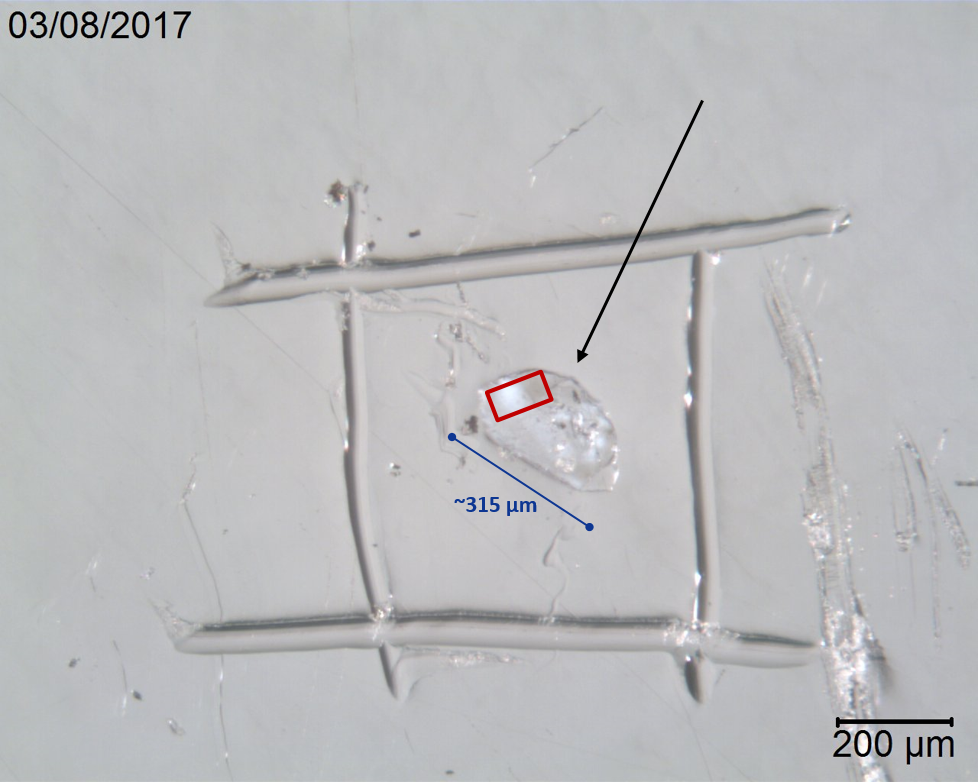
Let’s make a preparation for FTIR. Here is a tablet with a blue particle embedded in it. Two different magnifications show the context of the foreign blue particle. In the higher magnification, you can see that it’s actually partially embedded under the surface. That could be an important factor to help associate its placement in the tablet in context with the manufacturing process. Is it embedded or is it strictly impacted on the surface? That is an answer that can have significance on the history of the particle. Here’s the sample, viewed under a stereomicroscope with oblique illumination, pressed on a KBr plate, and ready for transmission micro-FTIR analysis. We have isolated the blue particle, removed a small sample from the blue particle, rinsed it, and prepared it for transmission micro-FTIR analysis. The sample we have prepared is about 315 µm in longest dimension. The sample is on a KBr salt plate, being observed in oblique illumination. Let’s watch the isolation and preparation process.

Because it’s a tablet, I’m going to start by adding a micro-droplet of water to soften the tablet and loosen the foreign particle. You see the micropipette, this time with particle-free water instead of amyl acetate. A micro-droplet of pf-water is allowed to sit on the surface; it sits for a minute or so. Using a tungsten needle, I start teasing the tablet around the foreign particle through the water. I will tease as much surface material off of the particle as possible, and eventually the particle will be loosened and released from the tablet. In this case, the particle floats—we’re not always that lucky.
The particle is teased in the water a bit more to remove as much tablet material as possible. Use a pair of curved, sharp tweezers to pick the particle up. Slide the tablet to another location and put a clean glass microscope slide under the particle, and turn on coaxial illumination, adjust it properly, and you can see as the particle is placed on the microscope slide there is still some tablet material on it. We want to reduce the amount of the adhering material, so there is another wash of the isolated particle. Increase the ratio of the water to the foreign material. Just play with it a little bit using the tungsten needle to dislodge additional clinging tablet material.
Bring the particle near the side of the droplet of water, and drag it out of the water. In the video, I’m pulling the microscope slide to the left; at the same time, I am moving my particle to the right until I move it far enough that it is no longer associated with the main droplet of rinse water. Now I can grab that water from under the particle with a tungsten needle and pull that to the side, taking contaminated water with it, and also allowing it to dry.
I am rotating the particle because I know that I want it in this orientation for my correct hand positions for sampling that particle. This particle is much too large for analysis of the whole particle. Using a micro scalpel, a small sample is cut off of the tip, and the remainder saved in case we need it for additional testing. I know that even the small sample removed from the main particle is too large for optimal sample preparation for transmission micro-FTIR, so about 80 percent of that sample is removed and moved back over here so we’ve got some to come back to later if we need it.
Now I’m going to use my roller tool. Typically, I want to go with the length of the particle. In this case, I know that’s not really going to matter that much since I’m fairly certain there aren’t multiple layers. I will go ahead and roll across the particle with the roller tool. There is our particle, nice and flat. I know that the particle is down around the 5-10 µm thickness range, which is a perfect thickness for FTIR infrared analysis.
We’re going to pick the particle up, this time without using any adhesive, and move the particle preparation slide away. Another slide that is holding a polished potassium bromide salt plate on double-stick tape is slid under the stereoscope. The illumination is switched from oblique to coaxial illumination so a lot of the surface scratches are now visible on the KBr. The particle is laid down on the surface of the KBr. The surface scratches and other minor surface defects make no difference to the analysis. It’s not contamination.
Now a small cover slip is picked up with the sharpened tweezers and laid on top of the particle. A tungsten carbide scribe is used to grab hold of the cover slip so we can press down and pull that glass across the sample. Some samples will smear, and other samples will just be embedded into the KBr so the sample is more firmly affixed to the KBr. In this area of the sample, you can see some small dark specks. At this point, I don’t know if that’s contamination or not. I’ll show you how we’re going to get around that here in a second.
We scribe a box around the sample so that when we leave our microscope area to go to the instrument we can locate it. Here’s what we’re going to do in setting up the analysis. We have a Nicolet™ system with a rectangular masking system, so I will mask the sample so that only the area within the square box will be analyzed—that’s what’s nice about pressing the small particle out—we’ve got about 315 µm to work with in particle size here and can analyze in several areas. Its relatively easily obtain a nice spectrum in the boxed area. In fact, in our next slide, the blue spectrum is from the exact particle that I recovered and analyzed in the boxed area, and the red spectrum is a polypropylene library reference sample.
I see we’re getting a little bit low on time, so I will quickly run through another example. This is a sample that some of you may have already seen. I use this demonstration often in presentations. Here, at the tip of the arrow, there is a faintly different colored red paint, slightly different colored than this thicker red layer. It was my job to determine if the thin layer was real or whether it was an optical illusion because of the black layer above it.
The entire sample is much too large to manipulate, so it needed to be trimmed down. A micro scalpel was used to make a very thin slice (cross section) of the paint chip. I cut away much of the paint in the cross section, leaving the area of interest, and placed it on a clean glass slide. As much of the extraneous paint as possible was removed so the particle could be rolled properly with a roller tool. I’ve got a little bit of a red; it’s just right in this tip area. Everything else is carved away and put to the side. Then I take the piece I have carved out and use the roller tool to roll the sample with the length of the layers. If you roll with the length—and when I say length, I mean going with the direction of the layers—what often happens is those layers will spread out and thin and you can decrease the contamination. If you roll across the layers, there is a greater chance of smearing or otherwise intermixing the adjacent layers. You can see a pretty clear-cut area here between the layers where you probably don’t have any cross contamination from one layer to another.
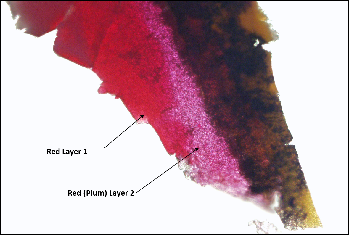
It is still too large for an appropriate sample for infrared analysis, so I go one step further and carve out a rectangle here in the more plum-colored area, staying as close to the center as possible, and similarly here in the dark red area. Both samples were then pressed on KBr for transmission micro-FTIR analysis producing these two samples. Again, this is in coaxial illumination because you can see all of the surface scratches on the KBr. You can easily see the red layer and what I call the plum layer. The infrared spectra for those two samples are seen in this slide. You can see the circled areas showing obvious differences. I know that those differences are due to different red pigments used to create the two different red colors. We’ve proven that there is a different red layer; that is due to a difference in the red pigment.
Let’s recap what we’ve discussed. We’ve seen that by simply looking at the samples we can determine a lot more information about the true nature of samples—things we simply can’t see macroscopically. We receive samples all of the time with an analytical request of “identify the black particle.” Generally, it’s not black—it’s probably gray, brown, dark blue, or dark green; it’s something other than what is appears to be macroscopically.
We can create homogeneous samples from heterogeneous materials. I showed you one technique, but there are multiple techniques. Another one I did not have time to show you is using a solvent to extract soluble material out of the particle. An example of that process might be plasticizers from plastics. But, anyhow, we can create homogeneous samples and that makes it much better to interpret the data more correctly. We’re not trying to make sense of data from multiple sources. Slightly different than that is that we simply create better preparations for instrumental analysis. Regardless of whether we’ve made them homogeneous or not, they’re simply better preps; we get better data. In some samples, we can make identifications that cannot be made in any other way. They cannot made by infrared data or through EDS data, so light microscopy can provide considerable useful additional information.
Finally, some problems are solved simply through microscopic observation; you don’t have to do anything else. It’s all you need, and you’re done. It’s very quick and easy, and you’re out of the project and on to the next one. Sometimes people spend hours going through instrumental analysis when a simple microscopic exam would solve the problem.
That’s where I’m going to stop for today. I’ve thrown a lot of material at you and now we can answer questions. One additional comment I do want to make is that I am a sixty-six-year-old man with arthritis in my hands. I can do this work. I did all of this analyses here. There’s no reason why you youngsters out there can’t do this work with a little bit of practice. So, get out there and try it and ask your questions.
CZ: Alright. Great. Thanks, Bill. Really interesting stuff there. Yes, thanks for everybody attending today’s webinar and go ahead and type in the questions box. Bill kind of answered the one that Jason posed early on in the presentation about “How do you create your own tungsten needles?” and Bill referenced our website. There are a few places you can locate that. One is on Modern Microscopy, which is our online free journal, and there’s a section in there called Prep School. So, lots of sample prep tips including tungsten needle making and sharpening. There is a video on our website, it’s about three or four minutes, on how to make a tungsten needle. So, I see some of the questions are really starting to roll in here, Bill. Let’s take a look at some of these.
“Do you polish the cut pieces of KBr before use, and after coming from the larger pieces?”
BC: Yeah, you start out with a large block of KBr, cleave that into your small piece, and then you polish that small piece. You can use water, ethanol, or methanol as a liquid, and it is polished wet and then polished dry. You have be careful not to let it sit in one spot too long.
CZ: Chantelle wants to know what we use for the organic adhesive.
BC: We use something called soluble gum that is not available publicly. We bought that years ago, and I don’t believe that you can get it. You can use rubber cement, anything like that, that you pre-test. I think rubber cement is what we have used; we use that in some other applications.
CZ: Ann asks, “What if the blue particle is water soluble? Would you lose it?”
BC: Yeah, Ann, that’s a risk you take. You have to start somewhere. Generally, I can look at a particle and in most cases determine at least the class of what that particle is. This one, I was able to look at it and I knew that it was most likely a piece of plastic, as opposed to a piece of sucrose, like a piece of lollipop or something like that, that might be water soluble. Those are the chances you take. If you do that, and you see it dissolving, you, as quickly as possible, try to remove the liquid or the particle. That’s always a chance you take.
CZ: Jan asks, “Do you prefer the roller and KBr plate above a diamond anvil? The diamond anvil is my favorite.”
BC: Yeah, my basic problem is that, a) I haven’t used a diamond anvil that much, but b) if you are subtracting out those bands in the diamond active region, it seems to me that they have to affect other bands that may be from an organic material. So, we tend to use the transmission as much as possible.
CZ: “Are tungsten needles ever reused?”
BC: Yes, tungsten needles are reused. I have a small jar and I have cut a circle out of a lid so there is just a ring that goes on the screws onto the jar, and I put a clean room wipe over that hole, and then I will wet an area of the cleanroom wipe with amyl acetate and then put needle up and down in that. The one thing that you do have to do is you have to have a separate needle for KBr and a separate needle for EDS. The reason for that is it’s very, very difficult to remove KBr contamination from tungsten needles, so you will often see KBr showing up in your EDS preps when it’s not part of your sample, and it’s a little difficult to explain.
CZ: “Is amyl acetate used?”
BC: Yes, we typically use amyl acetate as a universal solvent. It does have good solubility properties, but the main thing it has is a good surface tension, so that when you apply it to a smooth surface, it wants to create a dome; a nice droplet. When you put ethanol on a slide, it runs all over because it has no surface tension.
CZ: Jan asks, “KBr instead of sodium chloride?”
BC: Don’t know. I have used sodium chloride. It seems to me that it’s a little more fragile. KBr is pretty much been what everybody in my experience, or history, has ever used. Sometimes I will use a compression cell, and I use a pair of barium fluoride crystals. The problem with barium fluoride is that it is a very high cut-off wavelength. If you’re really lucky, you can go down to maybe 750–800 reciprocal centimeters. To tell you the truth, I don’t know, sodium chloride may cloud more easily. I’m just not sure. Not a very satisfactory answer. Sorry, Jan.
CZ: Linda asks, “How do you deal with static in keeping samples from jumping away?”
BC: Pray a lot. There’s a gun that you can buy called a Zerostat. Sometimes I get particles in a plastic bag, or particles in a petri dish, and I will zap them with the Zerostat. Sometimes you have to resort to using a little bit of liquid, a little water, or something like that, in order to stabilize the particle.
CZ: “Difference between coaxial and oblique?”
BC: Oblique light comes in from the side. It does not come in directly from the top. Oblique—it is a type of reflection, but it’s comes in at an angle from the side, whereas coaxial comes in straight down from the top, hits a particle, and bounces straight up off of it instead of coming off at a reflective angle.
CZ: Whitney wants to know, “Do you have a reference book you can recommend for trying to identify different fibers?”
BC: Probably the best thing to do is if you can get your hands on some SWIG-FIB information for fiber identification. If you were to email Scott Stoeffler at McCrone Associates, Scott could help line you up with that, he’s more into with fiber literature.
CZ: Hello, Troy. How are you doing, buddy? “What’s the cost difference between standard stereo and coaxial?”
BC: I don’t know; I’ll get back to you on that. I can tell you that my system is probably $25,000. The stereomicroscope that you saw, with all whistles and bells, so you’re probably adding another… I don’t know… $8,000 to it or something for the coaxial.
CZ: Pierce asks, “Can coaxial illumination be added to a scope in the field or is it too difficult to get?”
BC: That is a function of your ‘scope. I don’t know what brand ‘scope you have; any of the Olympus equipment is very simple—I believe any of it is fairly simple to retrofit—some of the other brands may not be. One of things you have to be careful of is if you’re buying a, what do I say, a lower, or a more economical system, they may not be able to accept coaxial illumination, so you’re just going to have to get with your ‘scope manufacturer and find out if they can do it, it’s no big deal at all to do it.
CZ: Jan wants to know about using ring light instead of coaxial and are they different.
BC: Yes, they are different, with coaxial illumination being much better than the ring light. It’s very different than ring light. It actually manipulates the light so that you can see things that you cannot see with the ring light.
CZ: Anthony wants to know, “How can I upgrade my stereomicroscope (Leica MD95) to coaxial?
BC: I’m not familiar specifically with that brand. I would get ahold of your Leica manufacturer, or you can get ahold of us here at McCrone and we can probably give you some assistance on making the correct contacts for doing that.
CZ: Okay, I think that does it for the questions Bill. We’ve answered quite a few. Again, we are able to follow up with people as we have your contact information, and Bill’s contact information is up on the screen; if you’d like to email him, feel free.
Comments
add comment